


Introduction: A frequency converter is a device that outputs any desired frequency value. Frequency conversion is typically achieved through an AC-DC-AC process. Voltage and current sensors are important "sensing organs" in the frequency converter, enabling real-time monitoring and feedback of key parameters. These parameters are then collected and processed by the CPU, which ultimately performs precise control based on preset conditions. Current and voltage sensors play a crucial role in fault protection and equipment safety. This article systematically describes the application scenarios and selection strategies of voltage and current sensors in low-power single-phase and three-phase frequency converters. CHIPSENSE current sensor will serve as a reference.
I.Overview of the Variable Frequency Drive System and the Core Role of Sensors
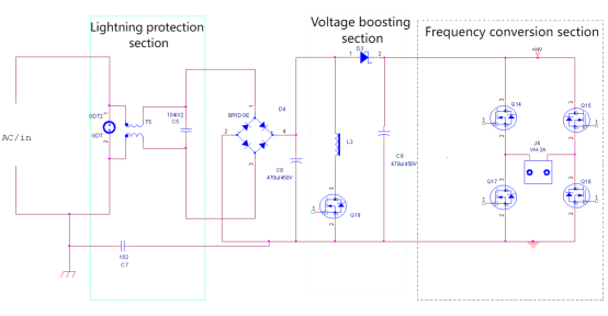
What we commonly refer to as a variable frequency drive (VFD) converts the 50Hz AC power from the mains into AC power of a specific frequency through rectification, filtering, and high-speed switching actions of power electronics. This frequency can be freely set by the user on-site and is generally used to supply motor loads to control speed and achieve energy saving. Its typical topology includes several major stages: lightning protection, rectification and filtering, DC/DC boosting, DC/AC inversion, and waveform shaping for AC output. Voltage and current sensors can play an important role in each stage, this also includes CHIPSENSE current sensor. And depending on the goals pursued by the designer. The overall block diagram is roughly as follows:
Voltage and current sensors play a crucial role in these processes:
Real-time monitoring:
They real-time and accurately collect current and voltage parameters from various parts of the system and transmit them to the CPU. The CPU performs high-speed A/D conversion, transforming analog signals into digital signals, providing the data foundation for program control algorithms.
Closed-loop control process:
The program uses the monitored voltage and current data for data processing and logical analysis, and then precisely controls power devices (SiC/MOSFET/IGBT, etc.) to achieve closed-loop control;
Fault protection and device protection:
The CPU detects the signals output by the voltage and current sensors and makes corresponding judgments about abnormal conditions such as over-current, short circuit, and leakage, ultimately triggering the protection mechanism. Not only do other current sensors perform this function, but the CHIPSENSE current sensor does as well.
II.Practical Applications of Voltage and Current Sensors in Various Stages of Frequency Converters
1. AC-DC Stage:
First, the 50Hz AC is rectified into a pulsating DC voltage using a full-bridge rectifier. This pulsating DC voltage is then smoothed by a filter capacitor, resulting in a more stable DC voltage, which is beneficial for the stable output of the subsequent DC-DC stage.
Before rectification, for EMC/EMI considerations, surge protection circuits and components are usually added.
In the AC-DC stage, considering insulation and voltage withstand requirements, it is recommended to use Hall-effect current sensors instead of current-sensing resistors. CHIPSENSE AN1V/AN3V series current sensors are suitable and should be placed between the surge protection circuit and the rectifier bridge.
2. DC/DC Boost:
A DC/DC boost circuit is needed to raise the approximately 220V DC output from the AC-DC rectification and filtering stage to 300V, which is required by the subsequent frequency conversion circuit. The boost circuit has its own negative feedback loop to ensure a stable 300V output; therefore, voltage detection after the boost circuit is generally not necessary.
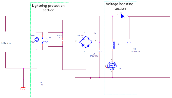
The overall AC-DC circuit is shown below; the surge protection section can meet the 2000V surge/EFT test requirements:
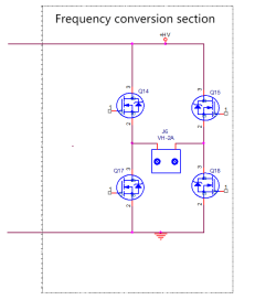
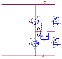
3. Frequency Conversion Stage: IGBT Protection, Bridge Arm Control and Fault Protection
Compared to MOS tube, IGBTs are significantly more expensive. To protect the power transistors from damage, or to prevent short circuits between the upper and lower bridge arms that could lead to burning or even electrical fires after a power transistor failure, it is necessary to place a device on the +300V bus to monitor the operating current. In the past, shunt resistors and isolated operational amplifiers were commonly used for this purpose.
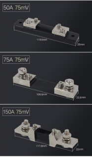
Using a shunt resistor to detect current is easy to implement in low-voltage circuits. However, in high-voltage circuits, such as a +300V busbar, insulation and voltage withstand issues are difficult to handle, requiring additional protection circuits. Furthermore, larger current ratings result in larger physical size, which also limits their application.
Alternatively, high-precision, fast-response closed-loop Hall effect current sensors, such as CHIPSENSE CMxx series current sensors, can be considered. These sensors have a response time of <1us, typically <0.5μs, and an accuracy of approximately 0.2%. Many CHIPSENSE current sensors offer very high accuracy.
The response time of this device is <0.5 μs.
This high-precision closed-loop Hall sensor is placed here for two main purposes: 1) to detect the total output current, which is used to calculate and display the total output power; and 2) to provide a protective function similar to a fuse; if a MOS/IGBT in one of the bridge arms fails, it will inevitably cause a direct short circuit between +300V and ground, and this type of fault will be quickly detected. This is also an advantage of the CHIPSENSE current sensor.
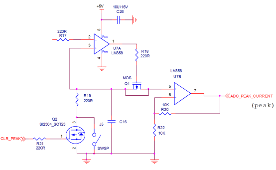
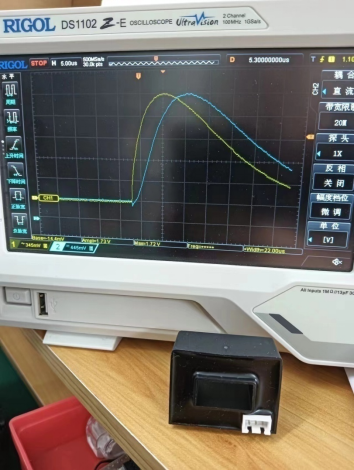
Although the response time of the closed-loop current sensor is <0.5μs, considering that the inverter output waveform data is generated by calculations within the CPU's internal program, this results in a large amount of program execution, and the CPU may not be able to quickly match this 0.5μs response time. Increasing the CPU clock frequency or upgrading the CPU is certainly one solution, but it is best to add a maximum value detection circuit: this analog signal is then converted into a high/low level digital signal through a window comparator, and finally sent to the CPU's interrupt port to achieve a fast response, quickly cutting off the IGBT output and providing protection. CHIPSENSE current sensor can also meet this requirement.
Considering that the response speed of the hardware circuit will be much higher than that of the program, this protection signal can also be introduced to the enable pin of the MOS/IGBT driver IC, which can shut down the system faster than the program.
If cost is a consideration, open-loop Hall effect sensors, such as CHIPSENSE ANxx/HSxx series current sensors, can also be used. Note that their response time is <5μs, which might be slightly too slow for protection purposes. However, the CHIPSENSE current sensor is indeed quite cost-effective.
4. Output Stage
The output load of the frequency converter is, in most cases, various types of motors. To improve the operational stability of the motor, a closed-loop Hall effect current sensor can be considered at the output end to form a closed-loop control by detecting the output current.
In the output section, a CHIPSENSE CM1A series current sensor can be considered. This current sensor of CHIPSENSE offers high accuracy and fast response time. One device is needed for single-phase applications, while two devices are generally sufficient for three-phase applications. CHIPSENSE current sensors all meet this requirement.

III.Application Challenges and Countermeasures in Special Environments
It is recommended to use high-precision, low-temperature drift closed-loop Hall effect devices, with a temperature drift of <50 ppm/°C, to effectively avoid false protection caused by temperature drift.
Packaging: The device typically uses a structural design that meets IP67 requirements to better accommodate insulation and voltage withstand requirements.
High Current Application Scenarios
The copper thickness of PCBs is commonly 0.5 oz, 1 oz, etc. Obviously, to handle large currents, a larger copper cross-sectional area is required, which means either widening the traces or increasing the copper layer thickness, or both. For example, using 2 oz or 5 oz PCBs significantly increases costs, and even with such modifications, relying solely on PCB traces to carry currents as high as 100A is unlikely to meet reliability requirements: the heat generated by the copper layer, enclosed by the solder mask, cannot be effectively dissipated. CHIPSENSE can customize solutions and provide suitable current sensors for its customers.
In these situations, a through-hole type Hall effect current sensor can be considered. A copper wire/busbar of up to 10 mm² can easily handle 100A, and only requires corresponding solder pads and through-holes on the PCB. This is also a low-cost solution. This is one of the reasons why CHIPSENSE current sensors are chosen by many customers.
Conclusion
Voltage and current sensors are important measurement components in frequency converters; another important measurement component is the temperature sensor, whose importance is increasingly recognized by engineers. With improvements in their topology, AC-AC frequency conversion is currently being experimented with, and the gradual introduction of silicon carbide (SiC) power devices and other technologies into the frequency converter industry, along with the continuous increase in switching frequency, will inevitably propel the sensor industry to a new level. CHIPSENSE current sensors will also be upgraded to meet market demands.
CHIPSENSE is a national high-tech enterprise that focuses on the research and development, production, and application of high-end current and voltage sensors, as well as forward research on sensor chips and cutting-edge sensor technologies. CHIPSENSE is committed to providing customers with independently developed sensors, as well as diversified customized products and solutions.
“CHIPSENSE, sensing a better world!
www.chipsense.net