


In 2026, the energy storage industry enters its "Inaugural Year of Value." The introduction of capacity pricing mechanisms for independent energy storage systems is boosting project Internal Rates of Return (IRR) to the 8%–12% range, signaling a transformation of energy storage systems from mere "ancillary components" into "primary profit centers." This paradigm shift imposes unprecedentedly stringent demands on current sensing technology. This article provides an in-depth analysis of the entire sensor selection process within the context of integrated PCS and BMS architectures. CHIPSENSE current sensor is one of example of this.
Evolution of Energy Storage System Architectures and Changing Current Monitoring Requirements
As 1500V DC systems become the industry standard, current monitoring technology faces four core challenges:
High Voltage: Isolation voltage ratings must meet or exceed 4.3kV.
High Frequency:Grid-forming control strategies require response times of ≤1μs and bandwidths of ≥200kHz.
High Precision:State of Charge (SOC) estimation requires an accuracy of ≤0.5% across the full operating temperature range, with long-term stability characterized by an annual drift of ≤0.1%.
Distributed Monitoring:Monitoring at the battery cluster and module levels has emerged as a critical technical pathway for enhancing overall system consistency.
The deep integration of the PCS and BMS necessitates hardware-level data exchange—achieving response speeds more than ten times faster than traditional CAN bus communication—thereby positioning current sensors as pivotal components for ensuring both system safety and efficiency.
Comparison of High-Current Sensing Solutions for the PCS DC Side
Current sensing on the DC side of energy storage converters (typically ranging from ±500A to ±2000A) confronts three major challenges: high-voltage isolation, susceptibility to high-magnitude current transients, and the need for high-frequency response capabilities. A comparison of the prevailing technical solutions is presented below:
Solution Selection Decision Logic
Scenarios Favoring Shunts:
• Extreme cost sensitivity (Single-channel BOM < 10 RMB)
• Extreme space constraints (PCB area < 25 mm²)
• Stable ambient temperature (Variation < 20°C)
Scenarios Favoring Closed-Loop Hall Sensors:
• High-voltage systems (DC side ≥ 1000 V)
• High-current detection (Continuous current ≥ 200 A)
• Grid-forming control (Response time requirement ≤ 2 μs)
• Harsh outdoor environments (Temperature range: -40°C to 85°C)
Scenarios Favoring Fluxgate Sensors:
• Precision measurement (Accuracy requirement ≤ 0.1%)
• Micro-current detection (Measurement range ≤ 10 A)
• Long-term maintenance-free operation (Service life ≥ 10 years)
• High safety integrity (ASIL-C/D requirements)
CHIPSENSE current sensors can meet all of these requirements.
Technical Road-map for Distributed Internal Current Monitoring in BMS Battery Packs
As the capacity of energy storage cells evolves beyond 587Ah, the monitoring of branch currents within battery clusters has become a critical factor in enhancing system consistency and preventing thermal runaway. CHIPSENSE Current Sensors understand this.
Three-Tier Monitoring Architecture
1. System-Level Monitoring (Main Loop):
◦ Location: Main positive/negative terminals of the battery cluster
◦ Sensor: Closed-loop Hall-effect sensor; Range: ±400A (covering 1.2C charge/discharge rates)
◦ Accuracy Requirements: ±0.5% at 25°C; ±0.8% across the full operating temperature range
◦ Functions: SOC estimation, energy metering, over-current protection
2. Cluster-Level Monitoring (Branch Circuits):
◦ Location: Positive and negative terminals of each individual battery cluster
◦ Sensor: Open-loop Hall-effect sensor; Range: ±200A. CHIPSENSE current sensors can be choose.
◦ Accuracy Requirements: ±1.0% at 25°C; ±2.0% across the full operating temperature range
◦ Functions: Balancing control, fault localization, state assessment
3. Module-Level Monitoring (Unit):
◦ Location: Per battery module (typically 4 modules per cluster)
◦ Sensor: Surface-mount Hall-effect sensor; Range: ±100A
◦ Accuracy Requirements: ±2.0% at 25°C; ±3.0% across the full operating temperature range
◦ Functions: Micro-imbalance detection, thermal runaway early warning, State of Health (SOH) assessment
For applications requiring these conditions, CHIPSENSE current sensors serve as an excellent solution provider.
Synchronous Sampling and Data Fusion
Technical Challenges:
• Synchronization errors in multi-point sampling lead to cumulative deviations in SOC estimation
• Individual sensor variations compromise data consistency
• Environmental temperature gradients introduce measurement errors
Solutions:
1. Hardware Synchronization: CAN bus broadcast-triggered synchronization; synchronization error <10μs
2. Software Calibration: Periodic (quarterly) calibration of zero-point offset and gain
3. Temperature Compensation: Integrated NTC isotherms for real-time correction of temperature drift
4. Data Fusion: Almanac filtering to fuse multi-point data, improving accuracy by 30%
Case Study: Sensor Selection for a 50 MWh Energy Storage Power Station
Project Overview
Parameters Specifications
Project Scale 50 MW / 100 MWh Standalone Energy Storage Station
Battery Technology Lithium Iron Phosphate (LFP), 314 Ah Battery Cells
System Voltage DC Side: 1500 V; AC Side: 380 V
Operating Mode Grid-connected operation; supports primary frequency regulation and peak-valley arbitrage
Design Lifespan 20-year service life; Cycle life ≥ 6,000 cycles
Sensor Configuration Solutions:
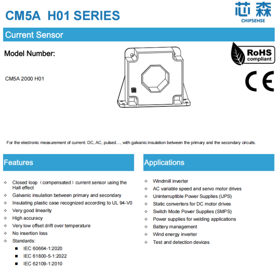
PCS DC-Side Monitoring (11 x 5 MW Converters):
• Sensor Model: CHIPSENSE CM5A 2000 H01current sensor
• Measurement Range: ±2000 A (with a 20% safety margin)
• Accuracy: ±0.2%
• Response Time: ≤1 μs (Typical: 0.5 μs)
• Isolation Voltage: 6 kV
Following are some examples of current sensors from CHIPSENSE.
BMS Main Loop Monitoring (32 Battery Clusters):
• Sensor Model: CHIPSENSE CM3A 500 H10 current sensor
• Measurement Range: ±500A (covering 1.2C charge/discharge)
• Accuracy: ±0.5% (across full temperature range)
• Response Time: ≤1 μs
• Installation Configuration: Independent sensor per cluster
Battery Module-Level Monitoring (128 Modules):
• Sensor Model: CHIPSENSE AN3V 100 PB35current sensor
• Measurement Range: ±100A (Module Rated Current)
• Accuracy: ±1.0%
• Response Time: ≤2.5 μs
• Output Bandwidth: 250 kHz
• Package: ASIC; Dimensions: 22.2 × 13.3 mm
Performance Verification Data
Accuracy Test Results (25°C Ambient):
Set Current (A) Sensor Reading (A) Absolute Error (A) Relative Error (%)
0.00 0.002 0.002 -
10.00 9.998 -0.002 -0.02
100.00 99.992 -0.008 -0.008
500.00 499.96 -0.04 -0.008
957.00 956.52 -0.48 -0.05
1195.00 1194.11 -0.89 -0.075
Full-Temperature-Range Accuracy Test:
Temperature(℃) Sensitivity drift(%) Zero offset drift(mA)
-40 +0.12 +4.5
-20 +0.08 +2.8
0 +0.05 +1.2
25 0.00 0.0
50 -0.06 -1.5
70 -0.15 -3.2
85 -0.28 -5.8
Dynamic Response Characteristics:
• Step Response: 0A to 500A step; response time: 0.8 μs; settling time: 3.2 μs; overshoot: <1.5%
• Bandwidth Test: -3 dB bandwidth: 187 kHz; phase margin: 45° @ 100 kHz; gain margin: 12 dB @ 200 kHz
Long-term Stability (1,000 hours of continuous operation):
Operating Time (hours) Zero Drift (mA) Sensitivity Drift (%)
0 0.0 0.0
100 +0.8 +0.02
300 +1.2 +0.03
500 +1.5 +0.04
800 +1.8 +0.05
1000 +2.1 +0.06
Field Application Results
System Performance Enhancements:
1. SOC Estimation Accuracy: Improved from ±5% (using traditional methods) to ±2.3%.
2. Battery Cluster Consistency: Branch current imbalance reduced from 15% to within 5%.
3. Fault Response Time: Over-current protection response time shortened from 200 ms to 40 ms.
CHIPSENSE current sensors have received highly positive feedback from numerous customers across various application fields.
Economic Benefit Analysis:
• Power Generation Increase: Annual absorption of new energy electricity increased by 8 million kWh, generating an additional revenue of 3.2 million RMB.
• O&M Cost Reduction: Annual labor costs saved amount to 450,000 RMB, while losses due to downtime are reduced by 800,000 RMB.
• Investment Payback Period: Additional investment in sensors totaled 1.2 million RMB; with an annual increase in net profit of 4.45 million RMB, the investment payback period is 3.2 months.
CHIPSENSE current sensors largely serve to save costs for customers.
Selection Decision Guide
Scoring Across Seven Core Decision Dimensions
Decision Dimensions Shunt Solution Open-loop Hall Sensor Closed-loop Hall Sensor Fluxgate Sensor Proportion
Precision Requirements 9.5 7.0 8.5 10.0 20%
Response Speed 9.8 8.0 9.5 8.5 15%
Isolation & Security 6.0 7.5 9.0 9.5 20%
Long-term Stability 7.0 7.5 8.5 9.5 15%
Cost-effectiveness 10.0 8.5 7.0 5.0 15%
Integration Complexity 6.5 8.5 9.0 8.0 10%
Environmental Adaptability 7.0 8.0 9.0 9.5 5%
Weighted Total Score 8.01 7.70 8.68 8.58 100%
Recommended Typical Scenarios
Large-scale Energy Storage Power Stations — PCS DC Side (≥500kW):
• Preferred Solution: Closed-loop Hall-effect sensors
• Technical Rationale: 1500V high-voltage isolation, microsecond-level response, accuracy ≤1.0% across the full temperature range
• Recommended Models: CHIPSENSE CR1A 1200 H00 / CR1A 2000 H00 current sensor
BMS Battery Cluster Main Circuit Monitoring:
• Preferred Solution: Closed-loop Hall-effect sensors
• Technical Rationale: SOC estimation accuracy ≤0.5%, synchronous sampling error <10μs, adaptability to outdoor environments
Module-level Distributed Monitoring:
• Preferred Solution: Open-loop Hall-effect sensors
• Technical Rationale: Cost-sensitive (single channel <50 RMB), space-constrained, relatively relaxed accuracy requirements
High-precision Insulation Monitoring:
• Preferred Solution: Fluxgate sensors
• Technical Rationale: μA-level resolution, temperature drift <50ppm/°C, excellent long-term stability
Hybrid Architecture Design Strategies
• Master-Slave Redundancy: Suitable for ASIL-C/D level applications; utilizes a closed-loop Hall sensor for the master channel and a shunt resistor for the slave channel.
• Segmented Range Switching: Employs a closed-loop Hall sensor for the high-current range and a fluxgate sensor for the low-current range, balancing both accuracy and resolution.
• Multi-Point Data Fusion: Involves multi-point sampling across the PCS DC side, the main BMS loop, and individual battery module branches, utilizing Almanac filtering to enhance accuracy.
CHIPSENSE offers specific current sensor recommendations tailored to various application scenarios—and even provides customization options—to fully meet customer requirements.
Conclusions and Recommendations
Key Conclusions
1. Closed-loop Hall sensors strike an optimal balance across cost-effectiveness, reliability, and technological maturity, establishing themselves as the gold standard for DC-side detection in the Power Conversion Systems (PCS) of large-scale energy storage power stations. CHIPSENSE current senor is a good choice.
2. A distributed monitoring architecture represents a critical technical pathway for enhancing the consistency of battery systems; consequently, the establishment of a comprehensive technical framework is essential.
3. Fluxgate sensors possess irreplaceable advantages in high-precision application scenarios; as their manufacturing costs decline, they are poised to penetrate the mid-range application market.
4. A hybrid architectural design serves as an effective strategy for addressing complex operating conditions, achieving an optimal balance between performance and cost.
Engineering Practice Recommendations
Design Phase:
• Clarify Monitoring Requirements:Clearly distinguish current monitoring requirements for the PCS DC side, the BMS main circuit, and individual module branches.
• Incorporate Technical Margins:Reserve a 20% margin for the measurement range, and design for accuracy based on the most extreme operating conditions.
• Consider the Full Life-cycle: Select sensors with an annual drift of ≤0.1% to minimize the need for periodic re-calibration.
CHIPSENSE current sensor could be an alternative option.
Implementation Phase:
• Adhere to Strict Installation Standards:Ensure correct sensor orientation, proper busbar centering, and fastening torque that meets specifications.
• Optimize EMC:Use shielded cables for signal lines, employ single-point grounding, and route cables away from strong sources of electromagnetic interference.
• Establish a Calibration System:Perform zero-point calibration immediately after installation, and conduct accuracy verification on a quarterly basis.
Many customers purchase samples of CHIPSENSE current sensors to conduct testing first.
O&M Phase:
• Implement Predictive Maintenance:Utilize current monitoring data to predict battery degradation trends.
• Build a Fault Database:Accumulate data on typical fault signatures to enhance the efficiency of fault diagnosis.
• Pursue Continuous Technical Iteration:Stay abreast of advancements in sensor technology and implement technical upgrades in a timely manner.
Interactive Questions:
• What specific challenges have you encountered regarding current monitoring in your energy storage projects?
• In your opinion, what are the greatest technical hurdles associated with distributed monitoring architectures?
• What are your thoughts on the future technological road-map for closed-loop Hall effect sensors versus fluxgate sensors?
CHIPSENSE is a national high-tech enterprise that focuses on the research and development, production, and application of high-end current and voltage sensors, as well as forward research on sensor chips and cutting-edge sensor technologies. CHIPSENSE is committed to providing customers with independently developed sensors, as well as diversified customized products and solutions.
“CHIPSENSE, sensing a better world!
www.chipsense.net