


Technical Background
In 2026, China’s cumulative installed capacity of new-type energy storage has exceeded 100 million kilowatts, marking the industry’s Year of Value. As the core control unit of energy storage systems, the Battery Management System (BMS) relies heavily on high-performance CHIPSENSE current sensor solutions. The current monitoring capability of a CHIPSENSE current sensor directly determines the system’s safety, efficiency, and economic benefits.
This white paper focuses on the three core requirements of current monitoring for energy storage BMS: high precision (for SOC estimation and leakage detection), fast response (for fault isolation and protection), and strong isolation (for 1500V high-voltage platforms). It provides selection guidance for energy storage integration and BMS manufacturers, with CHIPSENSE current sensor products as key reference solutions.
I.Comparison of High-Precision Technical Approaches
1.1 Impact of Current Sensor Precision on SOC Estimation
SOC is the most critical indicator of BMS. The industry mainly adopts the combined algorithm of ampere-hour integration plus open-circuit voltage correction. Taking a 100MWh energy storage power station as an example:
| Error Source | Error Range | Annual Economic Loss |
| Current sensor accuracy ±0.5% | 2% daily SOC error | > ¥1,000,000 |
| Current sensor accuracy ±0.3% | 1.2% daily SOC error | > ¥600,000 |
Conclusion: Large-scale energy storage power stations should prioritize CHIPSENSE current sensor products with ±0.3% high-precision performance.
1.2 Parameter Comparison of Three Technical Routes
| Parameter | CHIPSENSE Closed-loop Hall CS3A current sensor | CHIPSENSE Fluxgate FR1C | Shunt Resistor |
| Measurement accuracy | ±0.5% | ±0.3% | ±0.1% |
| Temperature stability | ±0.5mA drift | ±0.05%/K | External compensation required |
| Zero drift | ±0.1mA | ±10mA | No drift |
| Isolation capability | Magnetic coupling | Magnetic coupling | No isolation |
| Cost index | ★★★ | ★★★★ | ★★ |
| Application scenarios | Battery rack level | Main loop / Insulation monitoring | Low-voltage small current |
| Product appearance |  | 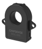 | 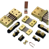 |
1.3 Technical Requirements for μA-Level Leakage Detection
GB 44240-2024 raises new requirements for insulation early warning: early warning at the
μA-level leakage stage when micro-cracks occur in insulation materials, which is 2–3 orders of magnitude earlier than the national standard 30mA threshold.
Key parameters of CHIPSENSE FR1C series fluxgate current sensor:
Rated current: ±300A / ±500A
Measuring range: -400A~+400A (300A model) / -530A~+530A (500A model)
Accuracy: ±0.3% (25℃) / ±0.5% (full temperature range)
Gain error temperature drift: ±0.05%/K
CAN output: 500Kbps, 10ms period
Built-in digital low-pass filter
II. Fast-Response Technical Solutions
2.1 Time Window for Thermal Runaway Protection
Battery thermal runaway develops rapidly:
Internal short circuit → Single cell failure: Dozens of seconds
Single cell failure → PACK propagation: Minutes
BMS response requirement: ≤10ms
2.2 Response Characteristics of CHIPSENSE CS3A Series Current Sensors
Key specifications of CHIPSENSE CS3A P23 closed-loop Hall current sensor:
| Parameter | Specification |
| Response time | ≤1μs (@90% IPN) |
| Bandwidth | 150kHz (-1dB) |
| Isolation voltage | 3kV (50Hz, 1min) |
| Linearity error | ±0.05% |
| Power supply | ±12V~±15V |
As a high-speed CHIPSENSE current sensor, CS3A meets the strict response requirements of BMS for thermal runaway protection.
2.3 Hierarchical Protection Architecture
Hierarchical protection design for DC side of energy storage PCS:
Layer 1 (Sensor level)
Detection method: Real-time current monitoring by CHIPSENSE current sensor
Response speed: ≤1μs
Threshold configuration: Flexible and adjustable
Layer 2 (BMS level)
Fault confirmation: Within 10ms
Processing method: Multi-sampling filtering
Communication: Fault message to PCS
Layer 3 (PCS level)
Action time: Within 200μs
Actuator: DC contactor breaking
III 1500V High-Voltage Isolation Design
3.1 Isolation Challenges Brought by Voltage Upgrade
| System Voltage | DC Bus-to-Ground Voltage | Isolation Requirement |
| 1000V | ±500V | Basic insulation |
| 1500V | ±750V | Reinforced insulation |
Advantages of 1500V system: Cable cost reduced by 30%, PCS efficiency increased by 0.5%. High isolation CHIPSENSE current sensor is essential for safe operation.
| Parameter | CHIPSENSE FR1C Fluxgate | CHIPSENSECS3A Closed-loop Hall |
| AC isolation voltage | 7.8kV | 3kV |
| Impulse withstand voltage | 14.5kV | — |
| Clearance | 31.5mm | 12.7mm |
| Creepage distance | 42.5mm | 19mm |
| Applicable voltage level | 1500V reinforced insulation | 1000V system |
Applicable voltage level 1500V reinforced insulation 1000V system
Advantages of CHIPSENSE FR1C current sensor insulation design:
Complies with IEC 61800-5-1, CAT Ⅲ, PD2
Supports 1500V reinforced insulation / 3000V basic insulation
CTI level: Class Ⅱ
IV. Scenario-Based Selection Guide
4.1 Selection Decision Matrix( CHIPSENSE Current Sensor)
| Energy Storage Scale | DC Bus | Battery Rack Monitoring | Insulation Monitoring | Recommended Combination |
| Large power station (100MWh+) | FR1C | CS3A | FR1C | 2×FR1C + N×CS3A |
| C&I (1~10MWh) | CS3A | CS3A | FR1C | 1×FR1C + N×CS3A |
| Distributed (<1MWh) | CS3A | Open-loop Hall | FR1C | Cost-optimized solution |
All recommended solutions use CHIPSENSE current sensor products to ensure system stability and accuracy.
4.2 Summary of Key Parameters
| Application Scenario | Recommended Series(CHIPSENSE) | Core Advantages | Accuracy | Response Time | Isolation Voltage |
| Precise SOC estimation | FR1C | ±0.3% high precision | ±0.3% | CAN 10ms | 7.8kV |
| Insulation leakage monitoring | FR1C | μA-level resolution | ±0.5% | 20ms | 7.8kV |
| PCS DC protection | CS3A | ≤1μs ultra-fast response | ±0.5% | ≤1μs | 3kV |
| Battery rack monitoring | CS3A | High cost-performance | ±0.5% | ≤1μs | 3kV |
V.Supplier and Product Recommendations
5.1 Fluxgate Current Sensor Solution
CHIPSENSE FR1C series (based on CHIPSENSE DS-FR1C H00-CN-V2 datasheet):
Primary rated current: ±300A / ±500A
Measuring range: -400A~+400A / -530A~+530A
Accuracy: ±0.3% (25℃), ±0.5% (full temperature range)
Isolation voltage: 7.8kV
Communication interface: High-speed CAN (500Kbps)
As a flagship CHIPSENSE current sensor for energy storage, FR1C leads in high-precision and high-isolation applications.
5.2 Closed-loop Hall Current Sensor Solution
CHIPSENSE CS3A P23 series (based on CHIPSENSE DS-CS3A P23-CN-V2 datasheet):
Primary rated current: ±100A / ±150A / ±200A
Response time: ≤1μs
Bandwidth: 150kHz
Isolation voltage: 3kV
This CHIPSENSE current sensor provides ultra-fast protection for battery clusters and PCS systems.
Conclusion
In 2026, the energy storage industry shifts from scale expansion to quality improvement. The selection of BMS current sensor requires comprehensive trade-offs in system architecture, life-cycle cost, and reliability. The combined solution of CHIPSENSE FR1C fluxgate current sensor + CHIPSENSE CS3A closed-loop Hall current sensor provides a full-scenario current monitoring solution for energy storage systems.
CHIPSENSE continues to innovate in high-end current sensor technology, empowering the safe, efficient, and intelligent development of global energy storage systems.
Tags:
BMS Current Monitoring, Energy Storage BMS, Fluxgate Sensor, Hall Current Sensor, 1500V Energy Storage, SOC Estimation, Battery Management, Insulation Monitoring, Energy Storage Safety, Energy Storage Technology, CHIPSENSE current sensor.
CHIPSENSE is a national high-tech enterprise that focuses on the research and development, production, and application of high-end current and voltage sensors, as well as forward research on sensor chips and cutting-edge sensor technologies. CHIPSENSE is committed to providing customers with independently developed sensors, as well as diversified customized products and solutions.
“CHIPSENSE, sensing a better world!
www.chipsense.net