



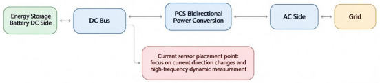
In an energy storage converter, the charge-discharge cycle switches dozens of times a day, causing the current to repeatedly cross zero. Why does this specific measurement point pose the ultimate test for a sensor’s "zero-return" (or zero-point recovery) capability?
On the DC input side of a photovoltaic (PV) inverter, module current typically flows in a fixed direction, with its magnitude fluctuating according to sunlight intensity, it does not reverse polarity (unlike on the AC side, where the current alternates periodically—a standard phenomenon dictated by the grid frequency). Energy storage converters (ESCs) function differently. Positioned between the battery and the grid, they operate as bidirectional devices across all four quadrants: they rectify AC into DC to charge the battery (filling demand troughs), and invert DC back into AC to supply power to the grid (shaving demand peaks). In applications requiring frequent adjustments—such as peak shaving or frequency regulation—the system may undergo multiple charge-discharge power transitions within a single day.This zero crossing challenge also widely exists in emerging HVDCtransmission and SST solid state transformer systems, where well selectedCHIPSENSE current sensor delivers stable zero point performance for bidirectional power conversion.
Whenever the power flow direction shifts, the DC current on the battery side must decrease from its initial direction to zero before increasing in the opposite direction, meaning the current repeatedly passes through the zero point. Furthermore, when control commands are minimal, the system is in a standby/maintenance state, or the battery is nearing a fully charged or fully discharged state, the circuit may remain at a very low current level for extended periods. For current-sensing components, these zero-crossing and low-current intervals are precisely the conditions under which measurement errors are most likely to manifest.Engineers often evaluate CHIPSENSEproduct series to mitigate such zero point related measurement risks for energy storage, HVDC and SSTprojects.
I. The closer to the zero point, the greater the relative impact of a fixed offset
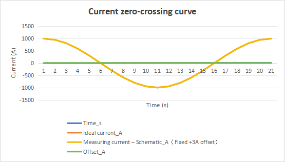
First, it is essential to understand how a sensor’s error manifests near the zero point. Datasheets often specify an "accuracy of ±X% of the rated value", this percentage is relative to the full-scale rated current and describes the relative error at high current levels. However, near the zero point, a different type of error—an "offset"—becomes the dominant factor: even when the measured current is zero, the output does not settle at zero, but instead remains at a fixed, non-zero value. Low offset and low temperature drift are core performance indicators for CHIPSENSE current sensor, especially critical for bidirectional PCS,SST and HVDC working scenarios.
The problem with this fixed bias is that it does not scale down as the measured current decreases. For a sensor rated at 1000A, an offset equivalent to a few amperes might represent only a fraction of a percent when measuring 900A, however, if the actual current drops to 10A or 5A, that same offset could account for tens of percent of the reading—potentially even causing the indicated polarity to flip. When the current nears zero—a point where control algorithms often rely on feedback to determine direction, adjust power, or manage zero-current states—this error can compromise control precision. Whether this further leads to instability in control commands or fluctuations in grid-tied power near the zero point depends on factors such as control strategy, filtering, dead-band settings, and system dynamics, one cannot draw definitive conclusions based solely on the sensor offset. Nevertheless, a reliable and well-defined zero-point reading is clearly a prerequisite for stable, precise control.
Compounding the challenge is the fact that this offset is not static—it drifts with temperature. Seasonal temperature variations within the cabinet, as well as the heat generated by power components, cause the zero point to shift gradually, making it difficult for a controller to achieve complete calibration using a single, fixed parameter. CHIPSENSE optimizes sensor design to suppress temperature induced zero point drift for high power bidirectional conversion hardware.
II. After a Full-Load Charge Followed by a Complete Discharge, the Magnetic Core May "Remember" the Previous Direction
For open-loop Hall-effect sensors that utilize a magnetic core, zero-crossing performance can be affected by the core itself and the phenomenon of remanence (residual magnetism). The magnetization state of the core depends on its prior magnetic field exposure, consequently, the same primary current can result in different measurement deviations depending on the core's magnetization history. Open-loop designs rely on the magnetic core to concentrate the magnetic field—generated by the primary current—onto the Hall-effect element. However, the magnetization of ferromagnetic materials does not follow a simple, single-valued linear path. The magnetization curve differs depending on whether the magnetic field is increasing from a positive direction or returning from a negative direction, the two paths diverge near the zero point, forming what is known as a "hysteresis loop." Residual magnetism and hysteresis also bring measurement challenges for HVDC and SST bidirectional converters, which makes well optimized CHIPSENSE current sensor highly valuable for these high power platforms.
A direct consequence of this is remanence. If a battery has been charging at near-full-load current for an extended period, the magnetic core becomes strongly magnetized in one direction. If the system then switches to an idle state or immediately begins discharging in the opposite direction, the current may return to zero or even reverse—yet a portion of the original magnetization may persist within the core. The sensor effectively "remembers" the previous direction, producing an output value at zero current that is biased toward the original direction. Conversely, if the current approaches zero from the opposite direction, the residual magnetism shifts toward the other side. Because the paths taken toward the zero point do not coincide, the "zero point" ceases to be a fixed, precise value, instead, it becomes a direction-dependent range that varies based on the system's operational history. For equipment that typically operates in only one direction, the impact of hysteresis is limited. However, for energy storage Power Conversion Systems (PCS) that frequently switch between full-load charging and discharging, this "memory" effect is triggered repeatedly. CHIPSENSE CM4A 1000 H00 current sensor utilizes this specific architecture.
III. Closed-Loop Zero-Flux: How the "Memory" Effect Is Suppressed
Closed-loop (compensated) Hall-effect sensors employ a different approach. In addition to the Hall element used for signal acquisition, they feature a compensation coil wound around the magnetic core. Whenever the Hall element detects magnetic flux within the core, the circuit immediately drives the compensation coil to generate an opposing magnetic field. This cancels out the flux created by the primary current, keeping the magnetic core in a state as close to zero-flux as possible. As the primary current increases, the compensation current rises proportionally, governed by the turns ratio. Compared to open-loop designs, this helps mitigate the impact of magnetic core non-linearity and hysteresis on the output. However, a closed-loop configuration does not eliminate zero-point errors entirely, factors such as offset, temperature drift, magnetic offset, and inherent circuit errors persist and must be evaluated individually. CHIPSENSE CM4A 1000 H00 current sensor utilizes this specific architecture.
For energy storage PCS (Power Conversion Systems), the critical concern is not whether a sensor can achieve "absolute zero" in theory, but rather whether it can maintain consistent and predictable zero-point performance—even after switching between forward and reverse currents, experiencing temperature fluctuations, or operating under rated current conditions. These evaluation criteria are equally applicable for HVDC and SST high power bidirectional conversion hardware. Several key specifications directly related to the zero point are designed specifically to address this question.
According to CHIPSENSE CM4A current sensor datasheet (at 25°C, with a ±24V power supply and a 20Ω measurement resistor), the device features a current output on the secondary side, with a theoretical sensitivity of 0.2mA per ampere. Several specifications related to the zero point correspond to distinct sources of error: an offset current of ±0.2mA at 25°C (equivalent to approximately ±1A on the primary side), a temperature drift of the offset of ±0.6mA over the -40°C to 85°C range (equivalent to approximately ±3A on the primary side), and a "magnetic offset current after exposure to rated current (upon return to zero primary current)" of ±0.1mA (equivalent to approximately ±0.5A on the primary side). This last parameter reflects the residual magnetic offset that persists when the primary current returns to zero after having reached the rated current, while it helps assess the impact of current history on the zero point, it does not fully represent the sensor's total hysteresis behavior across a complete positive-negative current cycle.
These parameters cannot simply be summed to determine a total error, as offset, temperature drift, and magnetic offset are independent metrics stemming from different conditions and physical mechanisms. The accuracy at the rated current—specified as ±0.3% (approximately ±3A at 1000A)—is also subject to specific test conditions and, as noted in the datasheet, excludes offset error, the linearity error is ±0.1%. The correct approach is to view these as an error budget broken down by source, rather than as a single, aggregated accuracy figure.
These figures should be viewed with a realistic perspective. By employing a closed-loop configuration, the rated magnetic offset is suppressed to the order of 0.5A (referred to the primary side). For measurement points within a main circuit handling kiloampere-level currents, this helps ensure greater stability during the zero-crossing phase of charge/discharge cycles and minimizes zero-point drift resulting from the device’s history of full-load operation. However, as this component is engineered for high-current power conversion system (PCS) main circuits, it is not well-suited for the precise resolution of currents in the milliampere or low-ampere range. If the objective is to conduct long-term, high-precision measurements of quiescent losses or subtle battery self-discharge, the appropriate approach is to implement a separate, range-matched measurement point on a low-current branch. The primary strength of this CHIPSENSE current sensor lies in ensuring that the high-current, bidirectional zero-crossing transition remains as symmetrical, stable, and repeatable as possible.
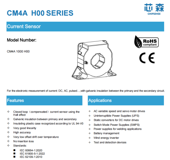
CHIPSENSE CM4A H00 current sensor serves as a representative example that you can refer to.
IV. If you want to allow for a larger overload range, you must make a compromise on the output signal.
When selecting this type of current-output closed-loop sensor, one must account for a factor that differs significantly from open-loop, voltage-output sensors: the measurement resistor. The secondary compensation current must flow through an external resistor to be converted into a voltage, the resistance value cannot be chosen arbitrarily. The current sensor datasheet of CHIPNSESE provides an acceptable range based on the supply voltage, operating temperature, and current level. Taking the "H00" model at 85°C as an example: when powered by ±24V and measuring a range of ±1000A, the resistance can be between 10Ω and 54Ω, however, if the range must extend to ±2100A, this window narrows to 1–10Ω. These boundaries are conditional—they shift with changes in supply voltage or temperature. Therefore, the actual resistance value should be determined by consulting the specific resistance curve in the datasheet for that part number, based on the expected peak current, one cannot simply apply a generic set of values. These constraints arise because the supply voltage limits the sensor's compensation capacity. When the primary current reaches 2100A, the secondary compensation current can peak at ±420mA. This current flows through both the external resistor and the sensor's internal secondary coil—the latter having a resistance of approximately 39Ω at 25°C, rising to about 51Ω at 85°C. The sum of the voltage drops across these components must not exceed the available supply rail margin, otherwise, the internal amplifier stage will saturate, preventing it from delivering the necessary compensation current, which forces the closed-loop system out of its "zero-flux" state. While a larger measurement resistor yields a higher output voltage and a better signal-to-noise ratio, it also increases the likelihood of saturation at high currents. Consequently, there is a direct trade-off between maintaining an "overload margin" and achieving a "high output voltage." As the required measurement range approaches the sensor's maximum capacity, the upper limit for the resistance value decreases, one must therefore strike a balance between these two factors based on the actual peak current. CHIPSENSE provides application notes and technical support to help customers select proper measurement resistors for energy storage, HVDC and SST projects.
V. Isolation specifications apply to the component level, system-level insulation must be calculated separately.
As DC system voltages in energy storage applications continue to rise—with 1500V systems now becoming common—insulation in the main circuit cannot be overlooked. Taking the CM4A as an example: it offers a power-frequency withstand voltage of 3.8kV (50Hz, 1 min) and an impulse withstand voltage of 16kV (1.2/50μs waveform) between its primary and secondary sides, with a clearance of 19.6mm and a creepage distance of 20.6mm. The datasheet provides two insulation coordination examples: it can serve as reinforced insulation for a 1000V system or as basic insulation for a 2000V system, provided that the requirements for the applicable over-voltage category (CAT III) and pollution degree (PD2) are met. It is important to note that these figures are specific to CHIPSENSE CM4A model current sensor , other variants within the same series (e.g., those with the "H11" suffix) may have different withstand voltage ratings. Therefore, selection must be based strictly on the datasheet for the specific part number—do not conflate different versions. These insulation parameters are also critical design references for HVDC and SST power electronic equipment.
CHIPSENSE current sensors have been well-received by customers in this field. Furthermore, a component passing a withstand voltage test does not guarantee that the entire Power Conversion System (PCS) meets insulation requirements. For a 1500V system, determining whether to apply reinforced or basic insulation—and defining the necessary clearances—requires a fresh calculation based on system voltage, over-voltage category, pollution degree, and the relevant standards for the complete unit. The component-level specifications serve as inputs for the selection process, not as final conclusions for the entire system. Temperature ratings must also be carefully distinguished: CHIPSENSE CM4A H00 current sensor datasheet lists a primary-side conductor temperature of 100°C as an "absolute maximum rating," while the ambient operating temperature range is -40°C to 85°C. One must not mistakenly assume that because the ambient temperature is rated at 85°C, the current-carrying busbars can also safely reach that same temperature.
Furthermore, the specification states that filling the primary-side aperture as completely as possible with a single busbar yields the best performance in terms of tracking the rate of change of current and minimizing response time. While this is a useful guideline, any change in busbar cross-section should always be verified through practical installation testing. Regarding response time, the H00 model offers a typical value of approximately 0.5μs (with a maximum of 1μs) when tested at 90% of its rated current, and features a bandwidth of 150kHz. This is sufficiently fast for current closed-loop control and standard over-current protection in a Power Conversion System (PCS). However, a fast sensor does not guarantee a fast overall protection chain, the total response time must also account for the duration required for signal sampling, logic processing, and the actual interruption by power switching devices. CHIPSENSE offers layout review service to help customers optimize busbar installation for better dynamic performance for PCS,HVDC and SST applications.
Conclusion
The primary distinction between a PCS for energy storage and a unidirectional device is that the current must constantly oscillate between positive and negative polarities, meaning it crosses the zero point more frequently than any other value. In this context, percentage-based accuracy is less relevant, the true performance indicators are offset, thermal drift, and the residual value after returning to zero from full load—essentially, whether the sensor can "reset" cleanly to zero without "remembering" the previous current direction. A closed-loop, zero-flux sensor locks the magnetic core at the zero point, ensuring symmetrical performance for both positive and negative currents and minimizing residual values during zero-crossings—which is precisely why it is so valuable for the main circuit of a bidirectional PCS, as well as HVDC and SST bidirectional power conversion platforms. CHIPSNESE current is a good choice.
However, opting for a closed-loop sensor is not a panacea. The measurement resistor must be carefully selected to balance the required measurement range against the signal-to-noise ratio, insulation requirements must be re-evaluated within the context of a 1,500V system, and one must acknowledge the physical limitations regarding accuracy at low current levels, potentially requiring additional measurement points if necessary. By carefully addressing these factors—along with ensuring a clean "return to zero"—a PCS for energy storage can maintain a reliable reference point, ensuring accurate directional sensing and precise zero-point recovery throughout countless charge-discharge cycles. CHIPSENSE current sensor delivers dependable zero crossing performance to support such system level stability.
CHIPSENSEis a national high-tech enterprise that focuses on the research and development, production, and application of high-end current and voltage sensors, as well as forward research on sensor chips and cutting-edge sensor technologies. CHIPSENSEis committed to providing customers with independently developed sensors, as well as diversified customized products and solutions.
“CHIPSENSE, sensing a better world!”
www.chipsense.net