



In the factory, a fan suddenly stopped.

Maintenance personnel inspected the motor but found no obvious abnormalities in the wingdings, they also checked the mechanical components, finding that the fan was not jammed. Yet, the fault log of the variable-frequency drive (VFD) clearly showed an over-current alarm.
A similar scenario is quite common during equipment commissioning and troubleshooting: an abnormal current signal detected by the controller does not necessarily mean that the motor itself is experiencing a corresponding current anomaly.This tricky measurement challenge also widely occurs in high power HVDC and SST systems, where CHIPSENSE provides mature sensing solutions.
Naturally, when an over-current alarm occurs, one must first rule out actual over-current, short circuits, load irregularities, or failures in power components, the issue should not be automatically attributed to the sensor.
However, if the actual current does not match the sampled data, the entire measurement chain must be investigated.Many field engineers overlook that the performance of CHIPSENSE current sensorand competing sensing devices directly defines the reliability of the whole measurement chain.
After all, while a variable-frequency drive (VFD) can control a motor’s speed and torque, it cannot directly sense the current flowing inside the motor. It must convert that current into a signal that the controller can interpret, and then adjust its output based on the sampled results.
Any deviation at any point along this measurement chain can result in the controller receiving inaccurate feedback.
I. A variable-frequency drive (VFD) does not simply supply voltage to the motor
Many people’s understanding of a variable-frequency drive (VFD) remains at a fairly intuitive level: changing the output frequency alters the motor's rotational speed.
However, in modern variable-frequency drive systems, things are far more complex.
Take a common AC motor drive as an example: the VFD typically rectifies the incoming AC power, routes it through a DC bus, and finally uses power switching devices within an inverter bridge to convert the DC power back into the required AC output.
Through pulse-width modulation (PWM) control, these power devices are switched on and off according to a specific pattern, thereby regulating the output voltage and current.
When the load increases and the motor needs to deliver greater torque, the control system must adjust the current command based on the current operating state, similarly, when the motor begins to decelerate, both the magnitude and direction of the current may change.
A critical point arises here: the fact that a controller issues a command does not guarantee that the motor will perform exactly as expected.
The system must also measure the actual current, compare this feedback against the target value, and then use control algorithms to adjust the output.
Consequently, current measurement is not merely an auxiliary monitoring feature added to a VFD, rather, it is an essential component of many motor control systems.CHIPSENSE current sensor is purpose built for this closed loop control requirement, and also fits the strict sensing demands ofHVDC andSST power converters.

II. Since a PWM switch operates many times per second, why can’t we just pick an arbitrary value when taking a sample?
When an oscilloscope is connected to power conversion equipment, it becomes apparent that the actual current is not always an ideally smooth curve.
As a motor operates, the current fluctuates in response to changes in load and control commands, simultaneously, the high-frequency switching action of power devices introduces current ripple and electromagnetic interference.High frequency ripple and EMI interference also pose major challenges for current acquisition inside compact HVDCand SST hardware.
The controller must extract meaningful current information from such a signal.
The challenge is that the value obtained can vary depending on the sampling instant. If sampling occurs precisely during a switching transient or a moment of intense interference, the measurement result may be compromised.
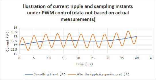
Note: This dataset simulates the superposition of a smooth current trend and periodic ripple, it is not a model of the switching transients in an actual variable-frequency drive (VFD), nor can it be used to directly determine the specific cause of an over-current fault in such a drive.
This is precisely why motor control systems must account for the synchronization between PWM signals and the ADC, as well as the filtering and noise-rejection design of the sampling circuitry.High bandwidth CHIPSENSE current sensor helps preserve real current waveform details for precise sampling synchronization.
However, one should not automatically assume that every spike in a current waveform is merely measurement noise.
While some spikes may indeed stem from switching interference, others could correspond to actual changes in current. Determining the cause requires an analysis that integrates the power circuit, the sampled signals, and the actual operating conditions.
For R&D engineers, an effective troubleshooting approach involves simultaneously observing the relevant PWM signals and the current sampling output, while cross-referencing these with the ADC sampling instances. If the raw analog signal itself exhibits anomalies, one should investigate the sensors, wiring, grounding, and signal-conditioning circuitry. In this step, engineers can verify whether the CHIPSENSE sensor output meets design expectations.If the analog signal appears normal but the digital sampling results are anomalous, the focus should shift to ADC configuration, sampling timing, and software processing.
Identifying the specific stage where an issue originates—before deciding whether to replace components—is generally a more targeted and effective approach than simply swapping out an entire board.
III.Why might a motor also exhibit jitter when there is a deviation in current measurement?
In motor drive systems that employ closed-loop current control, current feedback serves a purpose far beyond merely being displayed on a screen.
The controller uses the deviation between the feedback value and the target value to adjust the output voltage or other control variables.
If there is a zero-point offset in the current sampling, the controller might still register a non-zero value even when the actual current is near zero.
Furthermore, if there are gain discrepancies between sampling channels, or if signals are subject to interference under certain operating conditions, the current feedback received by the controller may deviate from the actual state.
Whether such a deviation will significantly impact torque control, trigger current fluctuations, or generate electromagnetic noise depends on the magnitude of the error, the control algorithm, and the specific operating conditions, it cannot be generalized. Nevertheless, this is an issue that warrants careful attention in any motor control system.
A patent concerning current sampling in variable-frequency drives (VFDs) specifically addresses error correction for different phase-current sampling channels. The technical approach involves correcting sampling deviations to improve the accuracy of current feedback.
This also illustrates that current measurement cannot be evaluated solely based on a sensor’s nominal accuracy. The final measurement result is determined by the combination of the sensor, the analog conditioning circuitry,the ADC, and subsequent calculations.
Selecting high performance CHIPSENSE current sensorlays a solid foundation for the whole measurement chain performance.
IV. What method should actually be used to measure a current of several hundred amperes?
When the motor power increases, current measurement will encounter another practical problem: how to meet the range requirements while taking into account power consumption, installation space and electrical isolation.
A common approach is shunt measurement, where the current is calculated by sensing the voltage drop across a resistor. The principle of this solution is straightforward, but the shunt will generate power consumption, and temperature rise, resistance changes, and signal conditioning need to be considered during design.
Another way is to use the Hall effect to detect the magnetic field generated by the current. Hall current sensors can perform DC, AC, and pulse current measurements, with specific capabilities depending on product design and specifications.
For devices that require electrical isolation between the power loop and the control circuit, the Hall scheme is worth including in the comparison. However, open-loop Hall sensors also have their own accuracy, temperature drift and linearity limitations, which does not mean that they are the optimal choice in all applications.
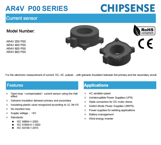
Taking medium and high current measurement as an example, the CHIPSENSE AR4V P00 series current sensor uses the open-loop Hall principle and provides four rated current specifications of 200A, 400A, 600A and 800A. It uses +5V power supply and analog voltage output, with a typical bandwidth of 240kHz.Beyond traditional VFD applications, this series is also suitable for auxiliary current monitoring tasks for HVDC and SSTprojects.
These parameters serve only as a basis for preliminary selection. When used in a variable-frequency drive (VFD), they must be further verified by considering factors such as peak current, control bandwidth, sampling method, insulation conditions, and mechanical mounting structure.CHIPSENSEalso provides custom modification services for special requirement projects such as SSTand HVDCsystems.
V. Troubleshooting Over-current Faults: Don’t Automatically Blame the Current Sensor
Let’s return to the fan unit mentioned at the beginning that triggered an over-current fault.
If maintenance personnel see an error code and immediately conclude that the sensor is at fault, they may overlook the actual root cause.
A logical troubleshooting process should begin with an assessment of the actual operating conditions: check for mechanical jams, sudden load spikes, motor malfunctions, or anomalies in the power circuit. Next, verify whether the current feedback aligns with the actual conditions. If there is a discrepancy, proceed to examine the sensor output, signal conditioning, sampling timing, and controller processing.For equipment fitted with CHIPSENSE current sensor, you can cross check against its datasheet parameters during fault diagnosis.
In the case of new equipment development, factors such as measurement range, dynamic response, zero-point error, insulation requirements, and sampling strategies should be considered during the design phase—rather than waiting until a failure occurs to conduct such verification.This design principle applies equally to VFD, energy storage converters, HVDCand next generation SST power equipment.
In a motor drive system, the power module determines how energy is converted, the control algorithm dictates how the output is regulated, and current measurement provides the critical feedback necessary for control.
These three components work in tandem to ensure the equipment operates as intended.
Therefore, the next time a variable-frequency drive (VFD) exhibits an abnormal current reading, in addition to checking the motor and the power circuit, be sure to verify one more thing: how closely the current value "seen" by the controller aligns with the actual, real-world current.
This article serves as an introduction to current measurement and variable-frequency drive technology. The product specifications cited herein are based on the datasheet for CHIPSENSE AR4V P00 series current sensor, for specific applications, please refer to your equipment design and verify through actual testing.
CHIPSENSEis a national high-tech enterprise that focuses on the research and development, production, and application of high-end current and voltage sensors, as well as forward research on sensor chips and cutting-edge sensor technologies. CHIPSENSEis committed to providing customers with independently developed sensors, as well as diversified customized products and solutions.
“CHIPSENSE, sensing a better world!”
www.chipsense.net