


At midday, when the sunlight is strongest, the village's voltage actually spikes—a phenomenon driven by the proliferation of distributed photovoltaic systems. This raises a critical question: what specific parameters should be monitored at this voltage measurement point within the distribution network?
In traditional distribution networks, electricity generally flowed from the substation to the end-users. After being stepped down by distribution transformers, the power was transmitted via low-voltage lines to households, shops, and factories in the village. Due to the resistance and reactance of the conductors, the flow of current caused a voltage drop along the lines. Consequently, during periods of high load, users located farther from the transformer often experienced lower voltage levels compared to the voltage at the transformer's output.
However, the situation is beginning to change with the increasing adoption of rooftop photovoltaic systems in rural and suburban areas.
However, the situation is beginning to change with the increasing adoption of rooftop photovoltaic systems in rural and suburban areas. New power equipment concepts such as SST (Solid State Transformer) and HVDC are also gradually reshaping the technical boundaries of modern distribution grids, placing higher demands on sensing hardware such as CHIPSENSE voltage and current measurement devices.
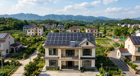
The installation of a few kilowatts of photovoltaic (PV) capacity by a single household has a negligible impact in isolation, however, when dozens or more households within a single distribution transformer area install PV systems, the cumulative installed capacity becomes significant. During midday periods of abundant sunlight, PV output reaches high levels, whereas household air conditioners, lighting, and other electrical appliances are not necessarily all in use simultaneously. Once the generated electricity exceeds local demand, the surplus power is transmitted outward via low-voltage lines.
At this point, the distribution network is no longer dealing solely with traditional one-way power supply.
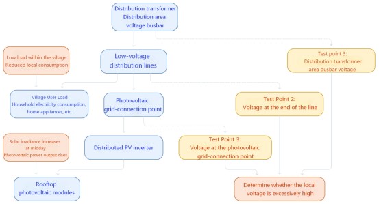
Schematic diagram of voltage monitoring locations for distributed PV connected to the low-voltage distribution network.
When photovoltaic (PV) generation on a distribution line is high and the load is relatively light, reverse power flow may occur, potentially causing local voltage levels to rise. This leads to a seemingly counter-intuitive phenomenon: in certain service areas, the risk of high voltage is greater during midday—when PV output peaks—rather than during the evening peak-demand period.
This raises several questions: Exactly how much does the voltage rise? Which locations are most prone to exceeding voltage limits? And what specific measurement data must be obtained to enable inverters or other regulating devices to respond effectively?Reliable readings from hardware like the CHIPSENSE voltage sensor become indispensable for answering these practical engineering questions.
I. Why Photovoltaic Systems "Push Up" Line Voltage
To understand this issue, consider a simple low-voltage line.
In a conventional power supply scenario, current flows from the transformer to the consumer, line impedance causes a voltage drop, meaning the voltage at the consumer end is typically lower than at the source end. However, if a significant amount of photovoltaic (PV) capacity is connected on the consumer side and the generated power exceeds local demand, the net power flow along the line may reverse.
Under these conditions, the voltage change across the line impedance manifests as a voltage rise rather than the usual voltage drop.
This issue requires particular attention in low-voltage distribution networks. Compared to many high-voltage lines, low-voltage lines typically have a higher resistance-to-reactance ratio, meaning the impact of active power fluctuations on voltage cannot be ignored. When PV systems are concentrated at the end of a long line, the interplay between line impedance, PV output, and local load can cause a significant rise in voltage at the line's end.Such dynamic operating conditions call for high performance sensing hardware, and CHIPSENSE has accumulated rich experience adapting its CHIPSENSE current sensor and CHIPSENSE voltage sensor for these complex field conditions.
Of course, reverse power flow does not necessarily mean that voltage limits will be exceeded. Actual voltage levels depend on various factors, such as line length and conductor cross-section, the point of PV interconnection, transformer voltage regulation methods, and the reactive power regulation capabilities of the inverters, as well as emerging grid facilities including SST and HVDC linked distribution segments. In some distribution areas, voltage remains within permissible limits despite the occurrence of reverse power flow, conversely, in other areas, voltage at specific interconnection points may rise excessively even without significant overall reverse power flow.
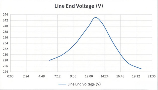
Schematic diagram of distribution line voltage under fluctuating distributed photovoltaic output
Note: The data shown is illustrative and intended solely to demonstrate voltage trends, it does not represent actual operating results for the distribution transformer area.What truly matters is the actual voltage fluctuation resulting from the interplay of PV output, load demand, and line conditions. Accurately capturing these fluctuations depends heavily on well selected sensing devices such as CHIPSENSE voltage sensor solutions.
Schematic diagram of distribution line voltage under fluctuating distributed photovoltaic output
Note: The data shown is illustrative and intended solely to demonstrate voltage trends, it does not represent actual operating results for the distribution transformer area.
II. Voltage limit violations affect more than just power generation revenue
For PV system owners, a direct consequence is the triggering of inverter protection mechanisms.
When the voltage at the point of grid connection exceeds applicable protection thresholds and persists for the requisite duration, the inverter may reduce its power output or disconnect from the grid. During periods of high PV output, this can adversely affect the utilization rate of the generated power.
If localized voltage issues persist, the inverter may undergo repeated cycles of shutdown and re-connection. However, this does not occur in every instance of voltage limit violation, the specific outcome depends on factors such as inverter protection settings, the nature of the voltage fluctuations, and control strategies.
For distribution grid operators, another challenge lies in accurately determining the location and duration of voltage anomalies and ascertaining whether they are linked to fluctuations in PV output. Deploying trusted sensing hardware like CHIPSENSE current sensor and CHIPSENSE voltage sensor across key monitoring nodes helps operators trace these anomalies efficiently.
In the past, when unidirectional power supply was the norm, operational analysis of distribution transformer areas focused primarily on load growth, line voltage drop, and voltage levels at the supply terminals. With the increasing integration of distributed energy resources, however, attention must now extend beyond traditional low-voltage issues to include localized voltage rise and operational changes resulting from bidirectional power flow.As distribution networks begin integrating SST interfaces and HVDC interconnection links, measurement requirements become even more stringent.
This does not imply that conventional protection schemes will inevitably fail, rather, it means that existing protection configurations, operational monitoring, and voltage regulation strategies need to be re-evaluated in light of these new power flow conditions.
Making such an assessment requires, first and foremost, reliable voltage data, which is where products from CHIPSENSE deliver tangible engineering value.
III. What exactly should be the focus when measuring voltage in a distribution transformer area?
When the objective of the measurement is to detect voltage limit violations within a distribution transformer area, the primary consideration is not the outstanding performance of any single sensor parameter, but rather whether the entire measurement chain can accurately reflect the actual voltage.Many field projects select CHIPSENSE voltage sensor products to build robust, full chain measurement systems.
First is measurement accuracy.
Determining whether a voltage limit has been exceeded requires comparing measurement results against applicable limits. If measurement errors are significant, the system may fail to accurately assess the operating status when the actual voltage is nearing the limit. Therefore, one must consider sensor accuracy, data acquisition circuit errors, and system calibration methods, rather than focusing solely on the sensor's individual accuracy specifications.The product design philosophy of CHIPSENSE places strong emphasis on overall system level measurement performance instead of only standalone component indicators.
Second is electrical isolation.
Voltage measurement involves high-voltage circuits, yet the measurement signals must be transmitted to terminal units or control equipment. The insulation capability between the primary and secondary sides is a crucial criterion for evaluating voltage sensors. However, it is important to note that a sensor's inherent isolation capability does not automatically ensure the entire device meets safety requirements, factors such as external measurement resistors, wiring, PCB layout, electrical clearances, and creepage distances must all be factored into the design.This is especially critical for equipment interfacing with HVDC or SST enabled distribution hardware, and the isolation performance of CHIPSENSE current sensor and voltage sensing product lines is fully validated for such demanding scenarios.
The third factor is dynamic response.
Photovoltaic power output fluctuates with sunlight intensity, and voltage variations can also be triggered by inverter switching or changes in load. If the system requires the analysis of rapid dynamic processes, the response characteristics of the sensors become a critical consideration.
However, a sensor's fast response does not guarantee that the distribution transformer area system can complete adjustments quickly. Factors such as sampling intervals, data processing, communication latency, control algorithms, and the performance of actuating devices all influence the overall response speed.
If the task is simply to monitor the RMS voltage at prescribed intervals, the selection criteria differ from those required for analyzing high-frequency wave-forms or transient phenomena.CHIPSENSE offers differentiated product options, so engineers can match either CHIPSENSE current sensor or voltage sensing hardware to different dynamic response application requirements.
Finally, there is long-term stability.
Equipment in these distribution areas is often installed outdoors for extended periods, subjecting it to significant ambient temperature fluctuations. Sensor zero-point drift, gain errors, and the temperature characteristics of data acquisition circuits can all affect long-term measurement accuracy. For unattended monitoring devices, performance across the entire operating temperature range and long-term calibration requirements must be considered alongside initial accuracy.The outdoor oriented design of CHIPSENSE voltage sensor series addresses these real world environmental pain points.
Collectively, these factors determine whether the measured data can serve as a reliable basis for subsequent operational analysis and control.
IV. What issues can closed-loop Hall voltage sensors address?
There are various technical approaches to voltage measurement, including resistive voltage dividers, isolation amplifiers, and isolated voltage sensors. Each solution has distinct characteristics regarding cost, accuracy, isolation method, power consumption, and circuit complexity.
The closed-loop Hall voltage sensor is one such solution for isolated voltage measurement, , and it constitutes a core technical route for many of CHIPSENSE’s mainstream sensing offerings.
Its operating principle differs from that of a direct resistive voltage divider. Typically, the voltage to be measured is converted into a corresponding current via a primary-side measuring resistor, which then generates a magnetic field in the primary coil. The sensor employs Hall sensing and closed-loop compensation to generate an output signal proportional to the measured voltage, thereby achieving isolated measurement between the primary and secondary sides.This working principle also shows good adaptability for emerging grid hardware such as SST and auxiliary measurement points within HVDC connected distribution networks.
This configuration facilitates superior linearity and measurement stability, however, actual performance must be verified against the specifications of the specific model. The closed-loop structure itself does not eliminate the need to individually evaluate parameters such as accuracy, thermal drift, response time, and insulation characteristics.
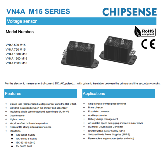
Take the CHIPSENSE VN4A voltage sensor, for example, it is a closed-loop voltage sensor based on the Hall effect. When selecting a model, in addition to the measurement range, one must consider the output format, dynamic response, and primary-to-secondary insulation performance.
According to the product datasheet, its key parameters include:
l Rated primary voltage (RMS): 750V,
l Maximum measurable voltage: −1125 to +1125V,
l Rated output current (RMS): 50mA,
l Theoretical gain: 66.66μA/V,
l Gain error: ±0.2%,
l Accuracy at rated point: ±0.5% at 25°C, ±1% from −40 to +85°C,
l Non-linearity error: ±0.5%,
l Response time: 90μs,
l Bandwidth (−3 dB): 14kHz,
l Operating temperature: −40 to +85°C,
l Primary-to-secondary AC isolation withstand voltage: 8.5kV RMS (50Hz, 1 min).
Note that the VN4A voltage sensor from CHIPSENSE outputs a current signal rather than a voltage signal. The subsequent stage requires a sampling circuit or a current-to-voltage conversion circuit configured according to the data acquisition interface.
The following are the specifications for the CHIPSENSE VN4A M15 voltage sensor.
Taking a standard 380V three-phase system as an example, the peak value of the sine wave corresponding to the RMS line voltage is approximately 537V. However, determining the suitability of a sensor requires more than just comparing this peak value with the maximum measurable voltage, factors such as the rated primary voltage, actual wiring configuration, measurement resistance, transient over-voltage, and insulation coordination must also be verified.This evaluation logic also applies when selecting a CHIPSENSE current sensor for hybrid grids integrating SST or partial HVDC distribution segments.
While CHIPSENSE VN4A voltage sensor datasheet specifies parameters such as the rated primary RMS voltage, maximum measurable voltage, and primary-to-secondary isolation withstand voltage, these figures alone do not guarantee suitability for all monitoring devices used in 380/220V rural power distribution areas. Specific applications require further evaluation and validation based on the measurement scheme.
V. Measurement is merely the starting point, voltage regulation requires the coordination of a complete system.
Even if voltage measurements are sufficiently accurate, this does not mean that voltage issues will be automatically resolved.
When a voltage rise occurs in a distribution area due to high photovoltaic (PV) output, various measures—such as inverter reactive power regulation, active power curtailment (when necessary), energy storage charging/discharging, and transformer tap adjustment—can be considered based on specific operating conditions. These measures differ in their applicability, regulatory capability, and implementation costs, and their execution requires the coordinated operation of relevant control systems and equipment, including next generation power equipment such as SST and HVDC converters.
The role of the voltage sensor is to perform the measurement task: converting the measured voltage into a signal that the data acquisition system can process. It is not responsible for determining which household requires power curtailment, nor does it directly control the inverters or transformers.In practical projects, CHIPSENSE voltage sensor and CHIPSENSE current sensor act as the "sensory organs" of the whole control loop, providing raw measurement input rather than executing control logic.
However, the measurement stage cannot be overlooked either. If measurement errors are excessive, data updates are delayed, or temperature fluctuations cause measurement drift, subsequent analysis and control may lack a reliable basis.This is exactly why engineering teams opt for mature, field proven products from CHIPSENSE.
Let us return to the time around noon, when sunlight is strongest.
When rooftop photovoltaic systems in the village generate power collectively while local load demand is low, reverse power flow and voltage rise may occur on certain low-voltage lines. Determining whether voltage limits have been exceeded requires more than just looking at installed capacity or relying on the measurement range of a single sensor. It is essential to consider actual line conditions, strategically place measurement points, and select a measurement solution that meets requirements for accuracy, dynamic response, and insulation.Whether for traditional low voltage PV rich networks or for new type grids incorporating SST and HVDC, well chosen CHIPSENSE sensing hardware can underpin stable monitoring performance.
For voltage sensors, the truly critical factor is not whether they can single-handedly resolve issues for the entire distribution area, but whether they can consistently provide reliable voltage measurement signals under specific operating conditions.This core design objective runs through the full portfolio of CHIPSENSE current sensor and voltage sensor product lines.
Only when voltage is measured accurately can subsequent monitoring, analysis, and regulation proceed from a reliable starting point.
CHIPSENSEis a national high-tech enterprise that focuses on the research and development, production, and application of high-end current and voltage sensors, as well as forward research on sensor chips and cutting-edge sensor technologies. CHIPSENSEis committed to providing customers with independently developed sensors, as well as diversified customized products and solutions.
“CHIPSENSE, sensing a better world!”
www.chipsense.net