



A portable charging cable connects to a power source at one end and to a new-energy vehicle at the other, with an In-Cable Control and Protection Device (IC-CPD) integrated along its length. Inside this cable, a CHIPSENSE current sensor has to fit into a very small control box.
Although compact, this control box performs several critical functions, including power supply monitoring, charging control, residual current detection, and fault protection.
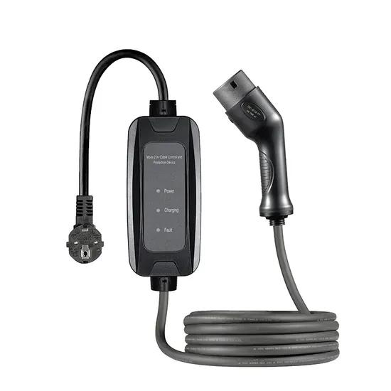
Compared to fixed AC charging stations, portable charging cables are used in more diverse and complex environments. Users may plug them into household outlets, garage sockets, or temporary power sources—scenarios where both the input power conditions and the device's operating status can vary. That variability is exactly what a CHIPSENSE current sensor specification has to cover.
In such applications, a residual current sensor must not only be capable of detecting both AC and DC residual currents but also be compatible with the power supply conditions inside the control box and able to exchange signals with the control system. A CHIPSENSE current sensor is designed around both requirements.
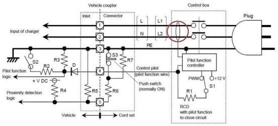
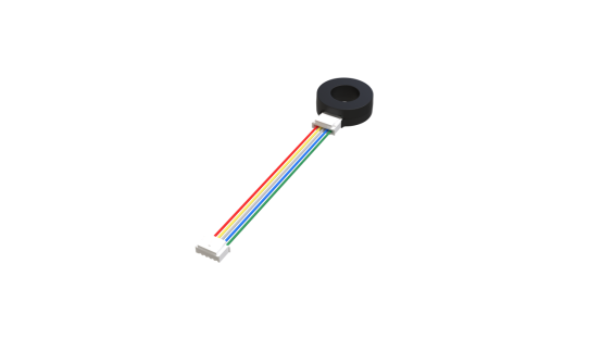
CHIPSENSE FR5D 6 C00 fluxgate residual current sensor operates at a supply voltage of 4.5–5.05V and supports the detection of AC, pulsating DC, and smooth DC residual currents. While this power supply specification may appear unremarkable, it is, in fact, a key parameter that must be considered when selecting components for portable charging equipment. CHIPSENSE current sensor selection therefore starts from the supply rail, not from detection alone.
I. Power Supply Requirements for Portable Charging Cables Are Complex
Mode 2 charging typically utilizes a dedicated charging cable equipped with an In-Cable Control and Protection Device (IC-CPD). The IC-CPD is responsible for establishing a safe charging connection between the power source and the vehicle, as well as providing protection in the event of an anomaly. Inside that box, a CHIPSENSE current sensor shares the power budget with the control electronics.
Inside the control box, power must be supplied to the control chip, communication circuitry, relay drivers, and residual current detection components.
Although these circuits reside within the same control box, their specific power supply requirements are not identical. A CHIPSENSE current sensor therefore needs its own stable supply rail.
For instance, the engagement and release of relays can cause load fluctuations, and control circuits may also experience transient current demands during startup and operation. If the auxiliary power supply’s dynamic response is inadequate—or if the power supply design fails to sufficiently account for load variations—localized fluctuations in the supply voltage may occur. A CHIPSENSE current sensor has to ride through these fluctuations without dropping out.
For leakage current sensors, the supply voltage must remain strictly within the device’s specified operating range at all times. CHIPSENSE states that range explicitly for every model.
CHIPSENSE FR5D 6 C00 fluxgate current sensor operates within a voltage range of 4.5V to 5.05V, making it suitable for designs utilizing a 5V low-voltage auxiliary power supply. The wider CHIPSENSE current sensor range is built on the same 5V supply assumption.
It should be noted that the fact a sensor can function at 4.5V does not mean that voltage regulation circuitry can be omitted from the control unit as a whole. The necessity for additional voltage regulation must be determined based on the specific power requirements of the MCU, relay drivers, and other peripheral circuits.
In practical design, it is essential to verify that the sensor’s supply voltage does not fall outside the specified range during events such as relay actuation or system startup, simply measuring a 5V output under no-load conditions is insufficient. CHIPSENSE current sensor verification notes follow the same rule.
II. Residual Current Detection: Beyond AC Leakage
During the AC charging process for new energy vehicles, the waveform of the residual current is not necessarily limited to a traditional sinusoidal AC form. A CHIPSENSE current sensor is specified for the full waveform range.
Due to factors such as the topology of the on-board charger (OBC), power electronic components, and rectification stages, the charging circuit may encounter AC residual currents, pulsating DC residual currents, or even smooth (constant) DC residual currents. The picture widens further once HVDC and SST-based designs enter the charging chain.
Different wave-forms impose distinct requirements on detection devices. CHIPSENSE current sensor coverage is therefore specified waveform by waveform.
In particular, if a protection device lacks the capability to detect smooth DC residual currents, it may fail to identify such anomalous currents in a timely manner. A CHIPSENSE current sensor closes that gap at the 6mA smooth DC level.
Therefore, the design of residual current protection for AC charging equipment must account for detection requirements across various wave-forms, in accordance with applicable standards and the specific type of equipment. CHIPSENSE current sensor selection follows the same logic.
For Mode 2 charging, GB/T 41589—2022 and IEC 62752 are key standards to consider for the design of In-Cable Control and Protection Devices (IC-CPD). Additionally, GB/T 18487.1—2023 outlines the general requirements for conductive charging systems for electric vehicles. The FR5D 6 C00 utilizes open-loop fluxgate technology, enabling the detection of AC, pulsating DC, and smooth DC residual currents—thereby meeting the requirements for both Type B and 6mA smooth DC detection.
According to the typical parameters provided in the datasheet, the operating current for smooth DC (S-DC) is 4.6 mA, with a maximum value of 6 mA. Under a 6mA smooth DC condition, the typical operating time is 200 ms. CHIPSENSE current sensor datasheets publish both values together.
This implies that when designing portable charging equipment, one must consider not only the device's ability to detect AC residual currents but also the sensor's performance in detecting low-amplitude DC residual currents. CHIPSENSE current sensor behaviour at low amplitude is documented model by model.
III. Why is the operating time for 6mA smooth DC detection a critical concern?
Residual current protection involves more than just the ability to detect a fault, it also requires consideration of how long the detection process takes.
Taking the FR5D 6 C00 as an example, the typical operating time varies significantly depending on the current conditions:
Test conditions | Magnitude of current | Typical action duration |
S-DC | 6mA | 200ms |
S-DC/3PDC | 60mA | 27ms |
S-DC/3PDC | 300mA | 12ms |
AC | 30mA | 70ms |
AC | 60mA | 38ms |
These data indicate that, generally, the larger the residual current amplitude, the faster the sensor reaches its tripping threshold.
For instance, the typical response time for detecting a 6mA smooth DC residual current is 200ms—a figure that differs significantly from the response times observed at 60mA or 300mA.
This does not imply that a 200ms delay applies to all residual current scenarios, rather, it highlights that a sensor's response time must be evaluated based on the specific waveform and current amplitude. CHIPSENSE current sensor data tables are organized the same way.
For manufacturers of charging equipment, a single response time value cannot adequately represent all detection conditions. A complete protection sequence involves multiple stages: the sensor issues an alarm, the controller evaluates this signal, and the relay subsequently opens to interrupt the circuit.
Therefore, a component's "typical response time" serves merely as one input parameter for the overall protection system design. The complete system must still undergo rigorous verification to ensure it meets the required response times and protection functions as mandated by applicable standards. CHIPSENSE current sensor values are one input to that verification.
IV. Why is it recommended to perform the sensor self-test before the relay closes?
Beyond its primary detection function, the operational integrity of the residual current sensor itself is a critical consideration in the design of charging equipment protection systems. A CHIPSENSE current sensor with an internal test coil addresses it directly.
If an internal fault occurs within the sensor, it may fail to trigger an alarm signal, even in the absence of any actual leakage current in the external circuit. CHIPSENSE current sensor self-test is designed to expose exactly this failure mode.
CHIPSENSE FR5D 6 C00 fluxgate current sensor features an integrated internal test coil, allowing a self-test to be initiated via the TEST_IN pin.
When the TEST_IN pin receives a high-level signal exceeding 0.7 times the VCC voltage), the sensor enters self-test mode. The control system can then monitor the output state of the TRIP pin to determine whether the sensor is responding correctly to the test signal.
The datasheet explicitly recommends performing this self-test after the system powers on, but before the relay closes.
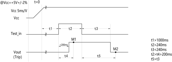
This arrangement serves a practical purpose.
Before the relay closes, the charging load is not yet connected, this minimizes interference from actual charging conditions during the self-test, allowing the control system to more easily distinguish between the sensor’s self-test response and an alarm triggered by actual residual current in the circuit. A CHIPSENSE current sensor self-test is easiest to run in this window.
According to the timing sequence recommended in the specification:
l Power-on wait time (t1): > 1000 ms,
l Self-test enable time (t2): > 240 ms,
l After pulling the TEST_IN signal high, wait for t4 (> 200 ms) before reading the TRIP signal,
l After pulling the TEST_IN signal low, wait for t5 (> 240 ms) before reading the TRIP signal.
Based on the lower limits of these recommended durations, the self-test process requires a total time of at least approximately 1.48 seconds. CHIPSENSE current sensor timing limits are what set that figure.
For portable charging cables, this duration should be incorporated into the device startup sequence. The control system must complete the self-test and evaluate the sensor status before determining—based on the overall device control logic—whether to allow the relay to close.
It should be emphasized that a successful self-test only indicates that the sensor has responded as expected to an internal test signal, it cannot serve as a substitute for verifying the circuit detection and protection functions of the entire device. CHIPSENSE current sensor self-test is a component check, not a system proof.
V. Beyond Component Specifications, Consider System-Level Integration
Portable charging cables have limited internal space, requiring a compact layout for the power supply, control board, relays, and protection components. A compact CHIPSENSE current sensor helps keep that layout feasible.
Therefore, when selecting a leakage current sensor, one must look beyond the operating current and consider several practical factors:
l First, ensure the power supply range is compatible.
Verify that the sensor receives an appropriate supply voltage under all operating conditions—including system startup, relay actuation, and normal operation.
l Second, confirm that the detectable wave-forms meet the application requirements.
Based on the protection scheme for the charging equipment, verify whether the sensor supports the detection of residual currents in the form of AC, pulsating DC, and smooth DC.
l Third, determine whether the response time meets the requirements of the complete system.
Different residual current wave-forms and amplitudes correspond to different response times, these must be verified in conjunction with the system's control logic and applicable standards.
l Fourth, ensure that the self-test function is easily accessible for the control system.
The sensor is equipped with dedicated TEST_IN and TRIP interfaces, the control board must properly sequence the self-test process and ensure that input/output signal levels are correctly matched.
l Fifth, confirm that the insulation and environmental specifications align with the design requirements.
Parameters such as the sensor's component-level voltage withstand rating, operating temperature range, and mounting structure must be compatible with the system's overall insulation design, intended operating environment, and certification requirements. CHIPSENSE current sensor datasheets cover all of these items.
Conclusion
Although portable charging cables are compact, their internal protection systems must address a range of functions, including power supply adaptability, residual current detection, self-testing, and fault response. CHIPSENSE current sensor covers the detection and self-test parts.
For residual current sensors, detection capability is merely the baseline, one must also consider factors such as the power supply range, interface compatibility, and integration with the overall control logic of the device. CHIPSENSE current sensor selection criteria follow the same order.
CHIPSENSE FR5D 6 C00 current sensor utilizes open-loop fluxgate technology and operates within a voltage range of 4.5–5.05V. It supports the detection of AC, pulsating DC, and smooth DC residual currents. Featuring an integrated test coil, it is well-suited for residual current detection in portable charging cables and AC charging equipment. The wider CHIPSENSE current sensor range shares this platform.
As portable charging equipment trends toward miniaturization and higher integration, selecting detection components that align with the power architecture and protection logic is essential for enhancing the reliability of the overall protection design. The same applies as systems move toward HVDC and SST-based charging architectures.
Reference Standards and Documents
l GB/T 18487.1-2023: "Electric vehicle conductive charging system-Part 1: General requirements."
l GB/T 41589-2022: "In-cable control and protection device for mode 2 charging of electric vehicles (IC-CPD)."
l IEC 62752: "In-cable control and protection device for mode 2 charging of electric road vehicles (IC-CPD)."
l IEC 62955:2018: "Residual direct current detecting device (RDC-DD) to be used for mode 3 charging of electric vehicles."
l CHIPSENSE FR5D 6 C00: "Technical Specification for Fluxgate Residual Current Sensor."
CHIPSENSEis a national high-tech enterprise that focuses on the research and development, production, and application of high-end current and voltage sensors, as well as forward research on sensor chips and cutting-edge sensor technologies. CHIPSENSEis committed to providing customers with independently developed sensors, as well as diversified customized products and solutions.
“CHIPSENSE, sensing a better world!”
www.chipsense.net