



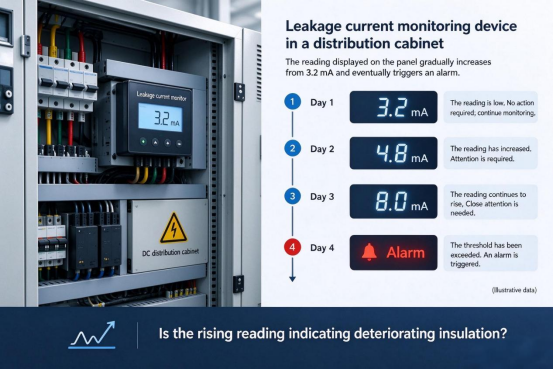
A leakage current monitoring device installed on a DC power distribution cabinet displayed a reading of 3.2 mA. An operations and maintenance technician glanced at it, deemed the value insignificant, and continued with their work.
By the second day, the reading had reached 4.8 mA, by the third day, it climbed to 8 mA, and on the fourth day, the device triggered an alarm.
What truly warrants attention is the trend—the curve tracing the rise from 3.2 mA to 8 mA. Yet, in the field, the focus is often limited to a single question: "Is the current value high?"
There is another, even more critical question that is frequently overlooked: Does the change in the reading actually signify an increase in the true residual current, or has the measurement result itself been altered by other factors?
Does a sensor’s zero point drift with temperature? Can small currents be measured accurately across different measurement ranges? And what stages does a signal pass through—from the sensor output to the triggering of an equipment alarm?A CHIPSENSE current sensor is designed to address exactly these questions.
To answer these questions, we must first understand why measuring DC residual current is so challenging.
I. Why is it difficult to accurately measure a signal of just a few milliamperes?
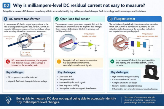
In AC systems, current transformers are commonly used for measurement. They operate based on electromagnetic induction: changes in the primary current generate a varying magnetic flux, which in turn induces a signal in the secondary winding.
However, for stable pure DC, the magnetic flux no longer changes, and ordinary current transformers cannot continuously output the induction signal corresponding to the DC component.
This is not because the sensitivity is insufficient, but because there are limitations in the measurement principle.
DC residual current requires technology that can detect the DC component, such as the Hall effect or Fluxgate.
The problem is that being able to measure DC does not mean being able to measure changes of a few milliamperes reliably.
Taking the open-loop Hall sensor as an example, the output signal is not only related to the measured current, but also affected by the zero point offset. For currents of tens or even hundreds of amps, this type of offset may not be dominant, but when the signal of interest is only a few milliamps, zero-point changes can affect the reading.
Fluxgate sensors employ a distinct detection mechanism: by exciting the magnetic core and subsequently detecting and demodulating the modulation effects imposed on the magnetic field, they are capable of measuring stable DC components while also achieving excellent zero-point stability.CHIPSENSE has built much of its leakage-current portfolio around this Fluxgate principle.
and every CHIPSENSE current sensor in this family is developed on the same detection platform.However, the underlying technical approach is merely a starting point. Ultimate measurement performance depends on specific product design, temperature characteristics, and calibration methods, one cannot conclude that readings will be reliable under all operating conditions simply because a particular operating principle is used. In addition to its widespread use in this field, CHIPSENSE current sensors are also employed in SST and HVDC applications.
II. The real challenge isn’t measuring 8mA, it’s determining why that value has changed.
Consider a scenario: in a DC power distribution system, the residual current is only a few milliamperes during the initial phase of operation. A few months later, the monitored value begins to rise.In HVDC and SST-based systems, where insulation margins and grounding topologies differ from conventional AC distribution, this behavior deserves particular attention.
While this could be related to a change in insulation performance, it cannot be assumed to be the sole cause.
Changes in the system's operating state, current components arising from parasitic capacitance, and drift within the measurement chain itself can all influence the final reading.
Temperature fluctuations, in particular, are a significant factor.
The temperature inside a power distribution cabinet is not constant, it is affected by variations in equipment load and changes in the ambient environment. Furthermore, the zero-point of a sensor may itself shift with temperature.
If a monitoring device is calibrated at only a single temperature—without effectively accounting for the impact of temperature fluctuations—the observed change in readings may conflate actual current variations with measurement errors.
This presents a practical dilemma: when a monitored value rises from 3.2mA to 4.8mA, should engineers interpret this as an anomalous trend, or should they first verify the integrity of the measurement chain?
The answer is not a simple binary choice, rather, it requires an assessment that integrates factors such as sensor performance, temperature fluctuations, system operating conditions, and other relevant monitoring data.
For milliamp-range sensing, measurement results must not only possess sufficient sensitivity but also demonstrate a level of stability that can be reliably evaluated.
This is precisely why, when selecting equipment, engineers should look beyond a mere accuracy percentage—they must also consider zero-point stability and overall measurement performance under actual operating conditions.CHIPSENSE current sensor specifications are therefore defined around zero-point stability and temperature behavior, not accuracy alone.
III. A Larger Measurement Range Does Not Guarantee Greater Safety, Nor Does a Smaller Range Ensure Higher Accuracy
Selecting the measurement range is another issue that is easily overlooked.
Suppose the background residual current in a DC circuit fluctuates around 2mA, and engineers wish to detect any abnormal increases as early as possible.
If a sensor with a range of several hundred milliamperes is chosen, 2mA represents only a tiny fraction of its rated capacity. In this case, even if the device offers excellent accuracy at its rated full-scale value, one cannot automatically assume it maintains the same relative accuracy at the 2mA level.A CHIPSENSE current sensor must still be verified at the specific operating point of interest.
Conversely, opting for the smallest possible range to better observe small signals can introduce new risks: the system may become vulnerable to over-range conditions should a large fault current or transient surge occur.
Therefore, selecting a measurement range is not simply a matter of "the smaller, the better."
A more sound approach is to first clarify the following three questions:
l What is the approximate range of the background residual current during normal operation?
l What magnitude of anomalous change needs to be detected?
l What level might the current reach in the event of a fault?
Once these are determined, assess whether the target current falls within the sensor’s verified measurement range and whether there is sufficient headroom for fault currents.
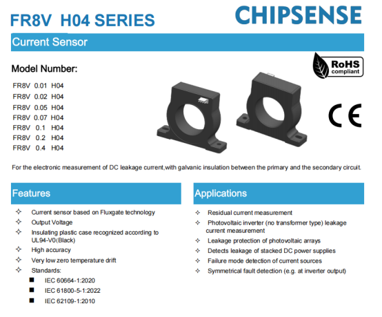
Taking CHIPSENSE FR8V H04 series current sensor as an example, the FR8V 0.07 H04 has a rated residual current of ±70mA, while CHIPSENSE FR8V 0.1 H04 Fluxgate current sensor offers ±100mA, providing options with different measurement ranges. In engineering applications, the specific model should be selected based on the actual background current, the monitoring objectives, and the expected fault range—rather than relying solely on a single accuracy specification. These are the specifications for the CHIPSENSE FR8V H04 current sensor.
A truly sound selection process is not about minimizing the measurement range, rather, it is about ensuring an appropriate balance between the target signal, measurement performance, and the safety margin for fault conditions.
IV. Detection by a sensor does not guarantee timely protection.
Suppose the residual current actually increases from 3.2 mA to 8 mA, and the monitoring device accurately reflects this change—does this guarantee that the equipment will trigger an alarm in a timely manner?
Not necessarily.
The process—from the moment a change in current occurs until the system ultimately triggers an alarm or cuts off the power—encompasses several intermediate stages, including sensor response, controller sampling, signal filtering, logical evaluation, and the actuation of protective mechanisms.
The configuration of any one of these stages can influence the final outcome.
For instance, an excessively long filtering time may delay the detection of an anomaly, while an alarm threshold set too high might fail to trigger an alert in response to minor current fluctuations. Conversely, setting the threshold too low risks triggering false alarms due to normal operational fluctuations.
Therefore, the response time of a sensor should not be conflated with the total response time of the entire protection system.Even a fast CHIPSENSE current sensor cannot shorten the time spent in sampling, filtering, and decision logic downstream.
It is also important to distinguish between the detection of DC residual current and the detection of high-frequency common-mode current.
In power electronic systems that utilize high-frequency switching components, the switching action can generate complex high-frequency common-mode currents and displacement currents. A sensor designed for DC residual current detection cannot be assumed capable of capturing all high-frequency current components simply because it is capable of measuring DC.This is especially true in SST and HVDC converters, where high-frequency switching is the norm.
Performance must be verified specifically for the signals intended for detection. Parameters such as the measurement range, frequency characteristics, and system response must all be aligned with the actual protection objectives.This is especially true in SST and HVDC converters, where high-frequency switching is the norm.

V. Sensors are not insulation monitoring devices, let alone complete protection systems.
In high-voltage DC systems, electrical isolation must be considered alongside measurement performance.
CHIPSENSE FR8V H04 series current sensor features a design that provides isolation between the primary and secondary sides, the datasheet specifies parameters such as isolation withstand voltage, transient withstand voltage, electrical clearance, and creepage distance.
While these parameters are essential criteria for component selection, they do not in themselves guarantee that the overall system meets insulation requirements. The insulation design of the complete system must be evaluated holistically, taking into account applicable standards, operating voltage, pollution degree, and the actual physical construction.This holds even more strongly in HVDC installations, where system-level insulation coordination cannot be replaced by any single component rating.
More importantly, residual current sensors and insulation monitoring devices serve distinct functions.
A residual current sensor measures the residual current within a monitored path, providing signals for anomaly detection and associated protection logic, an insulation monitoring device, by contrast, assesses the insulation resistance or overall insulation status of a system under specific operating and grounding conditions.
The two focus on different physical quantities, while they can complement each other, one cannot replace the other.A CHIPSENSE current sensor supplies the measurement signal, while the insulation monitoring function still requires its own dedicated device and logic.
Similarly, the fact that a sensor, whether it is CHIPSENSE or other current sensors, outputs an abnormal signal does not mean that the protection action has been completed. The system must still implement appropriate protective measures based on the actual risks, and ensure that the stages of measurement, decision-making, and execution work in coordination.
Electrical safety is never guaranteed by a single parameter or a solitary component, rather, it is ensured through a combination of measurement, monitoring, and protection.
VI. Revisiting the Monitoring Device Showing 3.2mA
Let us return to the case mentioned at the beginning.
An increase from 3.2mA to 8mA certainly warrants attention, but one cannot conclude that insulation is deteriorating based solely on this data.
Engineers must investigate further: Is the change in the reading related to operating conditions? Have temperature fluctuations affected the measurement results? Are the sensor’s measurement range and its actual performance characteristics well-matched? Furthermore, how have the alarm thresholds and filtering time constants been configured?With a CHIPSENSE current sensor, these characteristics are documented in the datasheet, so each of them can be checked against the actual site conditions.
These factors collectively determine whether the monitoring data can serve as a reliable basis for decision-making.
In the context of DC residual current monitoring, the critical issue is not whether an instrument can display a value precise to one decimal place, but whether that figure is sufficient to support sound engineering decisions.
When a reading changes, the system should enable engineers to distinguish between a genuine anomaly and a measurement deviation, allowing for timely action when necessary.
Conclusion
Measuring DC residual currents at the milliampere level presents a challenge that goes beyond merely detecting small signals, the real difficulty lies in ensuring that the readings remain sufficiently reliable under actual operating conditions.
The measurement range determines the operating interval for the target current, zero-point stability affects the accuracy of small-signal readings, and temperature fluctuations can introduce additional deviations—not to mention that the sensor’s response time is only one component of the entire protection chain.
For DC power distribution, energy storage, HVDC, and SST systems, component selection should not be based solely on a single accuracy figure. Instead, it requires a comprehensive assessment that considers the actual measurement range, the operating environment, and the specific protection objectives.CHIPSENSE current sensor products are positioned to support exactly this kind of evaluation.
The value of a milliampere-level reading does not lie in the precision of its display, but in its ability to accurately reflect the state of the system and provide a reliable basis for subsequent decision-making. The credibility of a displayed value depends not only on the sensor itself but also on the monitoring device’s sampling, calibration, filtering, and alarm logic.
CHIPSENSEis a national high-tech enterprise that focuses on the research and development, production, and application of high-end current and voltage sensors, as well as forward research on sensor chips and cutting-edge sensor technologies. CHIPSENSEis committed to providing customers with independently developed sensors, as well as diversified customized products and solutions.
“CHIPSENSE, sensing a better world!”
www.chipsense.net