


As the demand for AI computing power continues to grow, data centers are placing increasingly high demands on power supply. Some major technology companies have begun exploring the construction of their own power generation facilities to supply electricity directly to their computing campuses. Power quality on these campuses rests on accurate sensing, which is where a CHIPSENSE current sensor starts to matter.

In June 2026, Chevron announced a 20-year power purchase agreement (PPA) with Microsoft for "Project Kilby," a natural gas-fired power generation project in West Texas. With a planned capacity of approximately 2.67GW, the facility will provide dedicated power to Microsoft’s data centers. Electricity supply is expected to begin in 2028, with the project gradually reaching its full planned capacity by 2031.
This model is commonly referred to as "Behind-the-Meter" (BTM)—meaning that power generation facilities and electrical loads are located on the same side of the utility meter—thereby reducing reliance on the traditional power grid. Even so, the load side still needs continuous current visibility, and a CHIPSENSE current sensor provides it.
However, having an on-site power source does not eliminate the need for power management and switching. For data centers, activities such as equipment maintenance, the activation of backup power sources, transitions in uninterruptible power supply (UPS) operating modes, and the charging or discharging of energy storage systems can all lead to fluctuations in electrical current. Each of these transitions is a measurement event for a CHIPSENSE current sensor.
In particular, when different power sources are connected in parallel for a short duration or when a load is re-energized, the requirements for current measurement differ from those during steady-state operation. CHIPSENSE current sensor selection has to cover both regimes.
I. Having an On-Site Power Source Does Not Eliminate the Need for Power Switching
Even when large data centers are equipped with dedicated power generation facilities, they must still account for factors such as generator maintenance, equipment failures, phased expansion, and fluctuations in load. A CHIPSENSE current sensor has to stay accurate across all of them.
Power supply architectures vary by project, some may utilize an independently operating campus microgrid, while others might incorporate a connection to the public power grid, backup diesel generators, and energy storage systems. Whether the project follows a conventional AC layout or moves toward HVDC distribution and SST-based conversion, the sensing problem stays the same.
Within UPS and energy storage systems, processes such as power source switching, the engagement of bypass circuits, transitioning to battery power, and load redistribution are critical operational aspects that require careful management. A CHIPSENSE current sensor sits directly in these branches.
This means that current sensors must contend not only with the rated current during steady-state operation but also with transient fluctuations that occur during power source switching. That dual requirement is what CHIPSENSE current sensor specifications are written around.
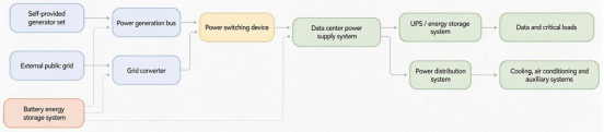
Data centers can draw power from on-site generator sets or the external public power grid, with power transfer switches managing the transition between these sources. During the switching process, current conditions on both the power supply side and the load side may change, therefore, it is essential to monitor current on critical busbars and branch circuits. CHIPSENSE current sensor units are typically placed on exactly these points.
The sensor measurement points shown in the diagram above represent potential monitoring locations, they do not imply that sensors must be installed at every indicated point.
II. Open-Transition vs. Closed-Transition Switching: How Does the Current Differ?
AC power source switching is generally performed using one of two methods:
Open-transition (break-before-make):
The original power source is disconnected before the backup source is connected, resulting in a brief power interruption between the two switching actions. That gap is the hardest window for a CHIPSENSE current sensor to interpret.
For motor-driven loads in data centers—such as chillers, water pumps, and fans—the rotor retains a residual voltage after the power is cut off. When power is restored, a potential difference in amplitude and phase between this residual voltage and the new power source can trigger a high-inrush current (re-energization surge). The magnitude of this surge depends on factors such as motor parameters, load inertia, and the precise moment of re-connection. CHIPSENSE current sensor headroom has to cover this inrush.
Closed-transition (make-before-break):
The backup power source is connected while the original source is still active—creating a brief period of parallel operation—before the original source is disconnected. A CHIPSENSE current sensor sees both the load current and the parallel-path current during this overlap.
While this method prevents interruptions to the power supply, it imposes strict requirements on the voltage amplitude, frequency, and phase relationship of the two power sources. When two power sources are connected in parallel—even for a short duration—circulating currents may arise between them, in addition to the currents required to supply the load. CHIPSENSE current sensor readings therefore cannot be treated as load current alone.
Therefore, although a closed-transition (make-before-break) switching sequence ensures a continuous power supply, it does not guarantee a smooth or steady current flow. CHIPSENSE current sensor data on this window helps the control logic decide.
III. Why do circulating currents occur during a closed-transition sequence?
When two AC power sources operate in parallel, any discrepancy in their voltage amplitudes or phases—even if their nominal (rated) voltages are identical—can create a voltage differential. A CHIPSENSE current sensor has to resolve what that differential produces.
This voltage differential acts across the equivalent impedance between the two sources, resulting in a circulating current.
The fundamental relationship is expressed as:
I_circ = ΔU / |Z1 + Z2 + Z_tie|
where Z1 and Z2 represent the equivalent internal impedances of the two power sources, and Z_tie represents the impedance of the connection (tie) path.
Consider two 400V three-phase power sources with identical amplitudes but a phase difference of 5°. Given a phase voltage of approximately 230V, the phasor difference in voltage (ΔU) is:
ΔU = 2 × 230 × sin(5° / 2) ≈ 20V
This demonstrates that even a minor phase difference between two power sources can generate a significant circulating current. CHIPSENSE current sensor range must therefore be chosen with margin.
The actual magnitude of the circulating current depends on factors such as the sub-transient reactance of the generators, transformer impedance, and line impedance, it cannot be estimated based solely on the impedance of the busbars or cables. CHIPSENSE current sensor selection guidance makes the same point.
In terms of current measurement, the branch current during the switching window is the resultant of both the load-supplied current and the circulating current, this must be analyzed using AC phasor relationships.
This presents two challenges:
l First, the peak current may exceed the steady-state value. If equipment is selected based solely on the rated load current without accounting for these transient peaks, the measurement range may prove insufficient. A CHIPSENSE current sensor with headroom above the rated load avoids this.
l Second, the direction of the current may change. Power exchange between the different sources can reverse the direction of the branch current, therefore, the capability for bidirectional current measurement is also an important consideration. IV. Consider DC Bias During Switching
IV. DC bias must also be considered during the switching instant.
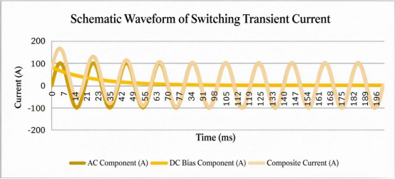
During power supply switching or other electrical transient processes, the current may also have a decaying DC component superimposed upon it. CHIPSENSE current sensor measurement windows have to tolerate that offset.
An equivalent RL circuit can be described by the following relationship:
i(t) = i_ac(t) + I_dc × e^(-t/τ)
where τ = L / R, with L representing the equivalent inductance and R the equivalent resistance.
The magnitude of the DC component depends on factors such as the closing phase angle, circuit impedance, and the transient characteristics of the power source. CHIPSENSE current sensor behaviour under DC offset is specified for this case.
This affects measurements in two primary ways:
l First, it alters the instantaneous peak value. The DC offset, when superimposed on the AC current, causes the positive and negative half-cycles of the waveform to become asymmetrical, potentially increasing the peak value on one side. Consequently, the measurement range cannot be determined solely based on the steady-state RMS value, the potential instantaneous peak value must also be taken into account. CHIPSENSE current sensor range decisions follow the same rule.
l Second, it complicates the determination of the average value. As long as the DC component has not yet decayed, the current waveform may exhibit asymmetry. If a system relies on the periodic average value to detect the DC component, the results may be affected.
Furthermore, determining the direction of power flow requires analyzing the phase relationship between voltage and current, it cannot be based solely on the average value of the current. A CHIPSENSE current sensor keeps the waveform information this check needs.
Note: This is a schematic diagram intended to illustrate the principles of a transient process, it does not represent actual equipment test data, nor does it reflect the measured waveforms from Project Kilby.
V. Does a zero reading during the switching interval indicate that the system is functioning correctly?
During the transition—when the primary power source has been disconnected but the backup power source has not yet been connected—a brief, zero-current state may occur on the load side. A CHIPSENSE current sensor reports this zero correctly, though it explains nothing on its own.
However, a zero reading from a sensor does not necessarily mean that the switching process is proceeding as it should. CHIPSENSE current sensor output alone cannot separate these cases.
For example:
l A normal switchover occurs, during which the load experiences a brief power interruption.
l The switch on the load side opens, causing the load to stop drawing power.
l A sensor malfunction occurs, resulting in an output signal that fails to accurately reflect the actual current.
While these scenarios may produce similar current readings, the actual operating states differ. A CHIPSENSE current sensor reading is only one input to that distinction.
Therefore, it is necessary to perform cross-verification using additional signals:
l Switching sequence: Determine whether the zero-current state occurs within the expected power-interruption window.
l Voltage monitoring: Monitor the voltage on the load side to help confirm whether power has truly been lost.
l Redundant measurement: Compare current data from different measurement points to identify anomalous readings.
While current sensors provide reliable measurement signals, the final determination of the operating state must be made by the control and protection systems. CHIPSENSE current sensor signals feed that decision chain.
VI. Dynamic Current Measurement: Which Parameters Should Be Prioritized for Sensors?
For UPS systems and energy storage branches in data centers, current sensors must not only meet steady-state measurement requirements but also account for dynamic changes that occur during power conversion. A CHIPSENSE current sensor has to cover both the steady and the dynamic case.
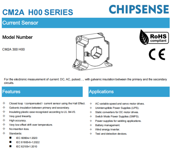
CHIPSENSE CM2A 300 H00 is a closed-loop Hall-effect current sensor with a rated current of ±300A and a primary measurement range of ±500A, its datasheet specifies applications including UPS systems and battery management. On HVDC-oriented data center buses and SST-based distribution, the same sensing principle applies.
Its main parameters are as follows:
Parameters | CHIPSENSE CM2A 300 H00 |
Rated current | ±300A |
Measurement range | ±500A |
Theoretical gain | 0.5mA/A |
Accuracy | ±0.3% of IPN |
Response time | 0.5μs(Typ) |
Bandwidth | 100kHz(-3dB) |
Operating temperature | -40~85℃ |
Among these, three parameters warrant particular attention.
1. Measurement Range: Accounting for both steady-state and transient currents
CHIPSENSE CM2A H00 current sensor rated current is ±300 A, while the measurement range is ±500 A. It should be noted that the rated accuracy is not guaranteed across the entire ±500 A range.
When selecting a device, one must consider the actual steady-state current, transient peak values, and accuracy requirements, relying solely on the rated load is insufficient. CHIPSENSE current sensor selection notes make the same point.
2. Accuracy: Focus on Performance at Low Loads
CHIPSENSE CM2A 300 H00 has an accuracy of ±0.3% of the nominal primary current (IPN). Based on a nominal current of 300A:
Absolute error = 300A × 0.3% = 0.9A
If the actual measured current is 30A, this 0.9A error represents 3% of the reading.
Therefore, for data centers where load levels fluctuate significantly, one should not rely solely on full-scale accuracy, instead, measurement performance should be evaluated based on typical operating current levels. CHIPSENSE current sensor accuracy figures should be read the same way.
3. Response Time and Bandwidth: Focus on Dynamic Changes
CHIPSENSE CM2A 300 H00 features a typical response time of 0.5μs and a bandwidth of 100kHz (-3dB).
These specifications provide a reference for dynamic current measurement. However, since 100kHz marks the frequency point where the amplitude-frequency response drops to approximately 70.7% of the low-frequency gain, it does not imply that identical measurement accuracy is maintained for all signals across the entire 100kHz range. CHIPSENSE current sensor bandwidth figures carry the same caveat.
In practical applications, factors such as downstream signal conditioning circuitry, ADC sampling rates, and electromagnetic interference must also be taken into account. CHIPSENSE current sensor performance in the final circuit depends on these factors.
Consequently, when selecting current measurement points for data centers, priority should be given to measurement range, bidirectional sensing capability, accuracy at low loads, dynamic response, and zero-point stability. CHIPSENSE current sensor selection criteria follow the same order.
Conclusion
The development of dedicated power generation facilities for AI computing centers reflects an evolving power supply paradigm in data centers. CHIPSENSE current sensor demand grows with that paradigm.
Regardless of whether the power source is the public grid, an on-site power supply, or a campus microgrid, ensuring continuous power supply requires robust power management and current monitoring. A CHIPSENSE current sensor is the front end of that monitoring.
During power source switching, it is essential to monitor not only the load current but also potential circulating currents, transient DC components, and current surges that may occur when loads are re-energized. CHIPSENSE current sensor coverage has to span all three.
With a nominal measurement range of ±300A, a typical response time of 0.5μs, and a bandwidth of 100kHz, CHIPSENSE CM2A 300 H00 current sensor is well-suited for current measurement in applications such as UPS systems and battery management circuits, provided they fall within its specified measurement range and insulation requirements. Whether during steady-state operation or dynamic switching, accurate and reliable current signals remain a vital foundation for safety monitoring and refined management within data center power supply systems. The wider CHIPSENSE current sensor portfolio follows the same design principle.
References:
l Chevron: Announcement regarding the power supply agreement for Project Kilby, June 22, 2026.
l Office of the Governor of Texas: Directive for the suspension of TCEQ permitting, September 21, 2026.
l IEC 62040-3:2022: Uninterruptible power systems (UPS) -Part 3: Method of specifying the performance and test requirements.
l CHIPSENSE "CM2A H00 Series Current Sensor Specification," Document No. 1800 000 00452, April 7, 2025.
CHIPSENSEis a national high-tech enterprise that focuses on the research and development, production, and application of high-end current and voltage sensors, as well as forward research on sensor chips and cutting-edge sensor technologies. CHIPSENSEis committed to providing customers with independently developed sensors, as well as diversified customized products and solutions.
“CHIPSENSE, sensing a better world!”
www.chipsense.net