



On October 26, the National Energy Administration (NEA) released national power statistics for the first nine months of 2026. At a press conference four days later, additional data regarding "new-type" energy storage (non-pumped-hydro storage) was unveiled: as of the end of September, the cumulative installed capacity of such storage systems reached 167GW (167 million kW) and 435GWh (435 million kWh)—a year-on-year increase of 63%. The average storage duration reached 2.61 hours (an increase of approximately 0.27 hours year-on-year), while the equivalent utilization hours reached about 915 hours (an increase of approximately 10 hours year-on-year).
Taken together, these figures reveal a clear trend in the energy storage industry: installed capacity continues to expand, the energy capacity per unit of power is rising, and systems are evolving toward longer durations.
For battery systems, an increase in storage duration implies a larger energy capacity configuration. However, for the Power Conversion System (PCS) and its associated current-measurement circuitry, the primary concern extends beyond mere battery capacity, it encompasses fluctuations in operating power, the requirements for bidirectional current measurement, and the potential for cumulative errors during long-duration energy integration.This is precisely the operating regime that CHIPSENSE current sensor products are designed to cover.
One metric, in particular, is frequently overlooked: zero-point offset.For longer-duration systems, CHIPSENSE treats this parameter as a first-order selection criterion rather than a secondary specification.
I. Longer Storage Durations Alter Operating Conditions for Measurement
The calculation for average storage duration is straightforward:
Storage Duration = Energy Capacity ÷ Power Capacity.
Based on the data released by the National Energy Administration:
435 GWh ÷ 167 GW ≈ 2.61 hours.
This indicates that the ratio of energy capacity to power capacity for new-type energy storage systems nationwide has reached approximately 2.61 hours.
It should be noted that this figure represents an average configuration metric based on the total installed capacity nationwide, it does not imply that all energy storage power stations operate at a 0.38C rate, nor can it be assumed that the actual operating current of the Power Conversion System (PCS) will necessarily decrease.
The current on the DC side of a PCS is primarily determined by power output and the DC bus voltage. Even if an energy storage system’s configuration is upgraded—for instance, from a 2-hour to a 4-hour duration—the current may remain unchanged, provided that the PCS output power and DC voltage stay the same.
In practice, however, energy storage systems do not always operate at their rated power. Factors such as dispatch commands, State of Charge (SOC) limits, thermal management, and specific charge/discharge strategies can often cause a PCS to operate under partial-load conditions for extended periods.
This presents a challenge for current measurement: as the actual operating current decreases, the fixed deviation—stemming from the sensor’s zero-point offset—accounts for an increasingly larger proportion of the measured value.A CHIPSENSE current sensor must therefore hold its accuracy at low current, not merely near its rated point.
Therefore, the measurement challenges posed by long-duration energy storage are not merely a matter of lower current levels, rather, operating conditions—such as low-power operation, long-duration integration, and bidirectional measurement—place more stringent requirements on zero-point stability.CHIPSENSE therefore specifies its energy-storage sensors around zero-point stability, rather than accuracy at the rated point alone.
Schematic diagram of the current measurement location on the DC side of an energy storage system’s PCS (Power Conversion System):

Note: The diagram illustrates a typical application principle, the actual sensor installation position and busbar configuration should be determined based on the specific design of the complete unit.
II. Bidirectional Current Measurement: Why Is the Zero-Point Offset Not Automatically Cancelled Out?
A key characteristic of the DC side of an energy storage Power Conversion System (PCS) is that the direction of the current changes according to the charge/discharge state.The same bidirectional requirement applies in HVDC and SST-based power conversion architectures, where energy flows in both directions between stages.
During charging, current flows in one direction, during discharging, the current flows in the opposite direction.
For a current sensor with a fixed zero-point offset, the measured value can be expressed as:
Measured Current = Actual Current + Zero-Point Offset.
Assuming the sensor has a positive zero-point offset:
l During charging, the measured current is higher than the actual value, leading to an overestimation of the total charge (integrated current).
l During discharging, the direction of the actual current reverses, the same positive offset causes the absolute value of the measured (reverse) current to be smaller, resulting in an underestimation of the total discharge.
Consequently, in the calculation of round-trip efficiency, the numerator decreases while the denominator increases, causing the calculated efficiency to be lower than the true value.
It is important to distinguish between electric charge (quantity of electricity) and energy. The integral for electric charge is:
Q = ∫I(t)dt
Whereas the integral for energy is:
E = ∫U(t)I(t)dt
The round-trip efficiency of an actual energy storage system typically concerns the energy charged and discharged, therefore, the impact of DC bus voltage fluctuations under different operating conditions must also be considered. The following calculation is intended solely to illustrate the effect of a fixed zero-point offset, assuming that charge and discharge voltages remain approximately constant and disregarding other potential measurement errors.
Taking the CHIPSENSE CM5A 2000 H00 current sensor as an example:
Its datasheet specifies a theoretical gain of 0.2mA/A and a maximum offset current of ±0.2mA. Based on the theoretical gain, this corresponds to a primary-side current offset of approximately ±1 A.
Assume a Power Conversion System (PCS) with a rated DC-side current of 2000A, a true round-trip efficiency of 90%, and equal durations for charging and discharging. Let the zero-point offset be 1A.
Under a 2-hour operating cycle, assume an average charging current of 1500A and an average discharging current of 1350A. Due to the zero-point offset, the charged energy is over-recorded by approximately 2Ah, while the discharged energy is under-recorded by approximately 2Ah. Based on this simplified model, the calculated round-trip efficiency is approximately 89.87%.
In the case of a 4-hour operating cycle, with the same total charge capacity, the average charging current drops to 750A, while the average discharging current is 675 A. Under these conditions, the charge and discharge capacities are over-recorded and under-recorded by approximately 4 Ah, respectively, resulting in a measured round-trip efficiency of about 89.75%.
Operating condition | Average charging current | Average discharge current | Calculate round-trip efficiency |
2 hours | 1500A | 1350A | About 89.87% |
4 hours | 750A | 675A | About 89.75% |
The same 1A zero-point offset results in a larger efficiency measurement deviation under 4-hour operating conditions.
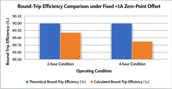
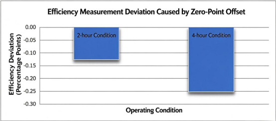
Round-trip efficiency measurement results under different operating conditions, given the same zero-point offset.This is the kind of deviation that CHIPSENSE current sensor selection guidance is intended to make visible before commissioning begins.
This does not imply that such a scenario occurs in all 4-hour energy storage systems, rather, it indicates that when the total energy capacity is similar but the operating current is lower, a fixed zero-point offset exerts a greater relative impact on the integrated energy value.
Furthermore, there is an often-overlooked characteristic: this type of deviation is not mere random noise—it will not necessarily cancel out simply by increasing the number of charge-discharge cycles measured. If the direction of the offset remains consistent with the operating conditions, it can persistently skew efficiency assessments.
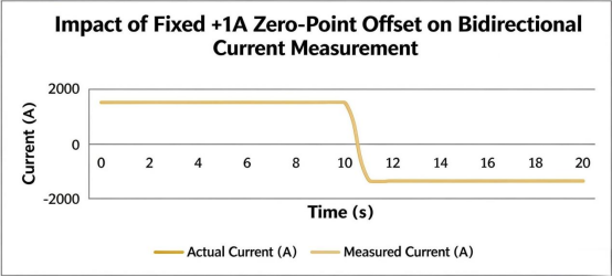
Why does a single zero-point offset cause errors in both charge and discharge measurements?
Note: This diagram follows the sign convention where charging is positive and discharging is negative. A positive offset (e.g., +1A) results in an overestimation of the charge current and an underestimation of the absolute value of the discharge current. The curves in the diagram are for illustrative purposes and do not represent actual measured wave-forms from CHIPSENSE CM5A current sensor.
III. Temperature variations can further complicate zero-point errors.
In addition to the initial zero-point offset, temperature variation is another factor that must be taken into account.
A common operating mode for energy storage power stations involves charging during off-peak (valley) hours and discharging during peak hours. This schedule—charging at night and discharging during the day—exposes the sensors and their peripheral circuitry to varying thermal environments.
The zero point of a current sensor does not remain perfectly constant across all temperatures. Temperature fluctuations within the device’s internal magnetic circuit, electronic components, or the surrounding installation environment can all influence the final output.
However, it cannot be assumed that a higher temperature automatically leads to a larger zero-point offset, nor can the direction of the temperature drift be predetermined.
If the zero-point shift during nighttime charging and daytime discharging happens to result in an overestimation of the charged energy and an underestimation of the discharged energy, the temperature variation could further amplify errors in efficiency measurement, conversely, it might partially offset them.
Therefore, assessing temperature drift cannot rely solely on a single test data point taken at room temperature. Instead, it requires verification based on the sensor’s full-temperature-range characteristics, the specific temperature profile at the site, and actual charge/discharge current data.CHIPSENSE current sensor datasheets therefore list offset temperature drift as a separate parameter, rather than merging it into a single accuracy figure.
For energy storage systems in long-term operation, zero-point stability should be treated as a distinct item within the error budget of the measurement chain, rather than being simply subsumed under a general accuracy percentage.This is why CHIPSENSE publishes zero-point and temperature-drift figures separately from rated accuracy.
IV. Efficiency Assessment During Operation: Beyond a Single Accuracy Figure
During the factory, installation, and commissioning phases, energy storage systems typically undergo performance verification under specified test conditions.
IEEE2030.3-2016 provides a framework for testing energy storage equipment and systems used in power applications, covering type testing, production testing, installation assessment, on-site commissioning, and periodic testing.
However, laboratory testing is not the same as long-term operational monitoring.
Once equipment is put into service, the on-site current sensors support functions such as control, protection, and operational analysis. Their measurement outputs are subsequently processed through signal conditioning, ADC sampling, digital filtering, and, ultimately, energy integration.
Even if a sensor itself boasts high rated-point accuracy, this does not necessarily reflect the actual accuracy of the entire measurement chain.
For instance, a sensor’s zero-point offset can lead to errors in current integration, temperature drift in a sampling resistor may alter the output scaling, and ADC bias or quantization errors can further impact the final results.
It is also important to establish a clear distinction: energy settlement for an energy storage power station typically relies on metering equipment at the grid-interconnection point (the "gateway"), whereas sensors internal to the Power Conversion System (PCS) are primarily used for equipment control, protection, and operational analysis. Since these two applications serve different purposes and are subject to different accuracy management requirements, they should not be conflated.
Consequently, internal measurement data is best suited for trend analysis and operational diagnostics. Determining whether a genuine decline in efficiency has occurred requires a comprehensive assessment that incorporates system-level energy metering alongside other potential sources of loss.
V. Low utilization hours does not mean that measurement can be relaxed
As of the end of September 2026, the equivalent utilization hours of new energy storage nationwide will be approximately 915 hours.
This data reflects the equivalent utilization level during the statistical period, not the actual operation of the equipment for only 915 hours. The energy storage system may be in low power operation, standby or auxiliary equipment operation state for a long time.
This also brings up another issue that is easily overlooked: the time window of efficiency statistics.
If only the charge and discharge window is intercepted to calculate the round-trip efficiency, the no-load loss of the transformer, the temperature control system and other auxiliary power consumption may be excluded, if the calculation is based on a longer natural time window, the auxiliary power consumption may have an impact on the overall system efficiency.
Therefore, the battery DC side round-trip efficiency, PCS conversion efficiency and system comprehensive efficiency including auxiliary power consumption need to clearly define their respective measurement boundaries.
There is also a common requirement for long-term operation of measurement links: the zero point must remain stable.
Because the comparison across days and months is not just the results of a certain charge and discharge, but also the accumulated power in different time periods. If the zero point drifts slowly, system efficiency changes may be mixed with measurement link changes, making operational diagnosis more difficult.This is precisely why CHIPSENSE treats long-term zero-point stability as a core criterion for energy-storage measurement points, and why CHIPSENSE current sensor specifications include dedicated drift entries.
VI. What should we pay attention to when selecting sensors for this type of measuring point?
Back to the device itself, the bidirectional high current measurement on the DC side of the energy storage PCS cannot only look at the rated current and rated point accuracy, but also needs to pay attention to the range, zero point, temperature drift, magnetic offset and dynamic response.
Take CHIPSENSE CM5A 2000 H00 current sensor as an example.
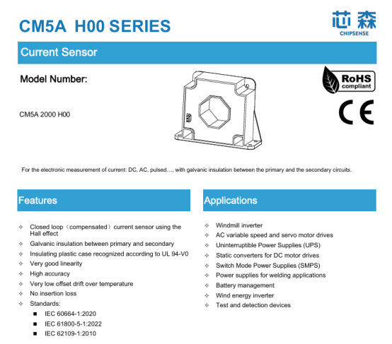
Regarding the zero-point, the datasheet specifies a maximum offset current of ±0.2mA, with a theoretical gain of 0.2mA/A—translating to approximately ±1A when referred to the primary side. The datasheet also provides figures for the temperature drift of the offset current (±0.2mA) and the magnetic offset current.
While these parameters cannot simply be summed, they should all be factored into the system error budget. This is particularly important for energy storage systems, which undergo frequent charge/discharge cycles and shifts in magnetic operating states, in such applications, one must consider not only the initial offset but also the stability of the zero-point during long-term operation.The same reasoning applies to HVDC and SST power stages, where DC-side currents are also measured continuously.
In terms of dynamic performance, CHIPSENSE CM5A 2000 H00 current sensor offers a response time of 0.5–1μs and a bandwidth of 150kHz, providing a solid performance foundation for dynamic current measurement in Power Conversion Systems (PCS).
Regarding isolation, the model features an AC withstand voltage of 6kV RMS (50Hz, 1 minute) and a transient withstand voltage of 23kV (1.2/50μs), with a clearance of 27.1 mm and a creepage distance of 29.1 mm between the primary and secondary sides. The suitability of this insulation must be verified against the specific voltage class, pollution degree, and insulation coordination requirements of the complete system.
Naturally, the sensor is only one component of the entire measurement chain. Elements such as sampling resistors, signal conditioning circuitry, ADCs, and digital processing stages also influence the final measurement results. Truly reliable efficiency monitoring requires verification at the system level.CHIPSENSE positions its current sensing products within exactly this full-chain framework.
Concluding
As energy storage systems evolve—moving from 2-hour to 2.61-hour durations and beyond—the shift entails more than just an increase in battery capacity, it also imposes new requirements for measurement and energy efficiency evaluation throughout the system's operational lifespan.
When it comes to high-current, bidirectional measurement, three key issues warrant attention:
First, accuracy should not be evaluated solely at the rated current. During low-power operation, a fixed zero-point offset can represent a significantly larger proportion of the actual operating current.
Second, one cannot assume that zero-point errors in bidirectional measurement will automatically cancel each other out. Depending on the direction of the offset and the specific charge/discharge conditions, such errors can consistently lead to an overestimation of the energy charged and an underestimation of the energy discharged.
Third, focus should not be limited to the initial zero-point. Factors such as temperature fluctuations, magnetic history, and the downstream sampling chain can all affect long-term measurement stability.
Ultimately, the efficiency evaluation of an energy storage system relies on the entire measurement chain. From sensors and signal conditioning to sampling and energy integration, every stage requires a clearly defined error budget.Selecting a CHIPSENSE current sensor is therefore only the starting point—the rest of the chain must be matched to it, and CHIPSENSE engineering support is intended to help customers make that match.In the era of long-duration energy storage, as battery capacities grow, measurement systems must place greater emphasis on errors that may appear minor but can accumulate significantly over time.
CHIPSENSEis a national high-tech enterprise that focuses on the research and development, production, and application of high-end current and voltage sensors, as well as forward research on sensor chips and cutting-edge sensor technologies. CHIPSENSEis committed to providing customers with independently developed sensors, as well as diversified customized products and solutions.
“CHIPSENSE, sensing a better world!”
www.chipsense.net