



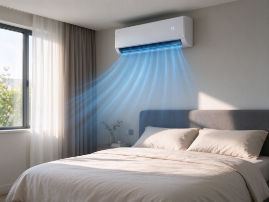
In the past, the current surge when the air conditioner was started was a very intuitive problem. The fixed-frequency compressor starts directly, and the current may increase significantly in a short period of time, and in severe cases, the lights may even flash.
Inverter air conditioners change this way of working. The driver adjusts the operating frequency and current of the compressor to gradually accelerate the compressor and reduce the current impact during startup.
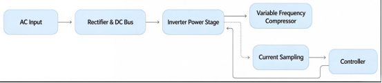
Since the startup phase has already stabilized, why is such a wide measurement range provided for the current?
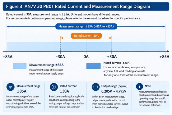
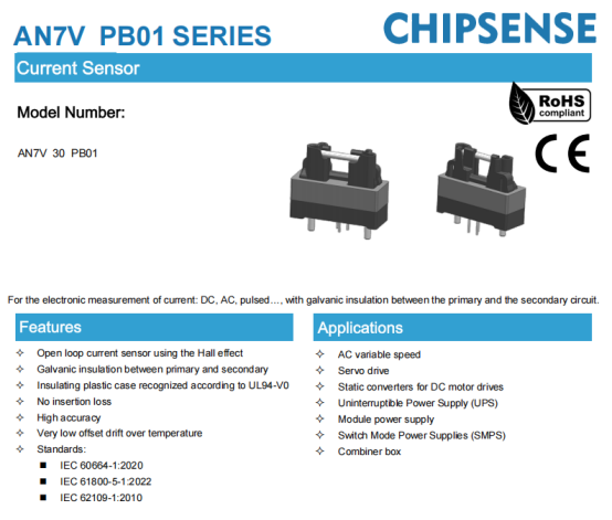
Take the AN7V 30 PB01 open-loop Hall-effect current sensor from CHIPSENSE as an example: it has a rated current of 30A, yet its measurement range extends to ±85A—approximately 2.83 times the rated current. At the same time, its accuracy specification is ±2%, indicating that it is not a device specifically designed for high-precision applications.
What is the rationale behind a sensor with a rated current of 30A and a measurement range extending to ±85A?
To answer this question, one must first understand the specific operating conditions that current measurement must contend with in the context of driving a variable-frequency compressor.
I. Startup Has Become Smoother, Yet Current Is Not Always Constant
The startup control of an inverter air conditioner is designed to address the current surge that occurs when a compressor transitions from a stationary state to an operational one.
However, once the compressor enters normal operation, the current continues to fluctuate based on factors such as operating frequency, load, the state of the refrigerant, and control commands.
For instance, when cooling demand rises suddenly, the compressor must increase its output capacity, similarly, during heating, low-temperature startups, or shifts in load, the drive system must adjust the motor's operating state. Consequently, the magnitude and rate of change of the current can vary depending on the specific operating conditions.This is exactly where a reliable CHIPSENSE current sensor helps the controller track such dynamic changes in real time.
More importantly, a distinction must be made between normal operation and abnormal operation.
If a compressor experiences mechanical jamming, an abnormal load, or other drive-related faults, the motor current may rise rapidly. While inverter drives are equipped with current-limiting and fault-protection mechanisms, this does not mean that current monitoring can overlook such abnormal conditions.
The controller must still determine—based on current feedback and other operational data—whether to adjust the output, limit the current, or shut down the power devices.
Consequently, selecting a current sensor cannot be based solely on the compressor’s rated current, nor can the measurement range be determined simply by the peak current observed during a standard startup.
Designers must also account for the potential amplitude and duration of abnormal currents, and verify whether the sensor can maintain the required measurement performance under such conditions.
However, there is a subtle distinction often overlooked: a larger measurement range does not necessarily make a sensor a better choice.
If sensitivity is sacrificed to achieve a wider measurement range, the output variation corresponding to normal operating currents will decrease, making it more difficult to measure low currents and process the resulting signals.
The measurement range, sensitivity, and measurement accuracy must be carefully balanced according to the specific application. Among the many suppliers available, CHIPSENSE stands out as one that offers excellent performance across all key metrics for its current and voltage sensors.
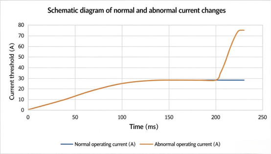
Important Note: The data in the table above is hypothetical and intended for illustrative purposes only, it does not represent actual measured results for the CHIPSENSE AN7V current sensor, nor does it reflect the specific startup or locked-rotor current of any particular air conditioner model. When finalizing the chart, please include a note below it stating: "Illustrative curve, data not based on actual measurements."
The 75A current value is used solely to demonstrate that current can occasionally exceed the normal operating range, it does not imply that such a current level will occur in all variable-frequency compressors.
II. Why does a device with a 30A rated current have a measurement range of ±85A?
Let’s look at CHIPSENSE AN7V 30 PB01 current sensor.
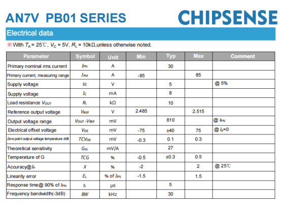
According to the datasheet from CHIPSENSE, this model has a primary rated current of 30A and a measurement range of −85A to +85A, with a theoretical gain of 27mV/A.
Taken together, these parameters reveal a key characteristic: the measurement range is not limited to the vicinity of the rated current, instead, it provides additional headroom for larger currents in both the positive and negative directions.
Based on the theoretical gain of 27mV/A, when the primary current is 30A, the output—relative to the zero-current reference point—changes by approximately:
30A × 27mV/A = 810mV.
When the current reaches 85A, the corresponding theoretical change in the output is approximately:
85A × 27mV/A = 2.295V.
CHIPSENSE AN7V current sensor operates from a single 5V power supply, with its output varying around a zero-current reference voltage. As the calculations above indicate, a change in current corresponds to a specific range of output voltage variation, the available swing of the output stage is therefore a key factor to consider during the design process.
It should be noted, however, that one cannot conclude—based solely on the supply voltage and theoretical gain—that the ±85A measurement range is determined strictly by the output stage approaching the power supply rails. The specific design basis should always be verified against the official product development documentation.
From an application perspective, it is crucial to recognize that "rated current" and "measurement range" are not the same thing.
Rated current reflects the device's current capacity under specified operating conditions, whereas the measurement range describes the span of current that the device is capable of measuring. A measurement range of ±85A does not imply that the device can operate continuously at 85A under all conditions, nor does it mean that the error remains constant across the entire range.
Consequently, when designing a compressor drive, one cannot determine the suitability of a sensor based solely on a 30A figure. It is also necessary to evaluate the actual current waveform, the duration of peak currents, linearity, and the system's protection thresholds.
This is precisely why selecting a current sensor based only on its rated current is insufficient, the true requirement is to ensure that the device’s measurement capabilities are properly matched to the actual operating currents. CHIPSENSE current sensors perform very well in this regard.
III. Is an accuracy of ±2% insufficient?
Beyond its measurement range, the accuracy specification of CHIPSENSE AN7V current sensor also warrants discussion.
At 25°C, this model offers an accuracy of ±2%—a figure that is not particularly remarkable when compared to certain current sensors designed for high-precision measurement.
However, determining whether a sensor is suitable for a specific application requires looking beyond just the accuracy figure.
In motor drive systems, current measurement can serve various functions. For instance, some control algorithms require precise current feedback to facilitate current regulation and torque control, while other functions focus primarily on whether the current exceeds a preset threshold or whether any anomalous changes are sufficiently pronounced.
Different functions impose varying requirements on accuracy, dynamic response, and measurement range. CHIPSENSE current sensors offer a wide range of measurement capacities, and can even be customized to meet specific customer requirements.
For applications focused on monitoring high-current threshold violations—provided there is an adequate margin between the normal operating range and the protection threshold—a sensor with an accuracy of ±2% may suffice, once factors such as sensor offset, gain error, thermal drift, noise, and sampling delay are factored into the error budget.
Of course, this does not imply that an accuracy of ±2% will automatically satisfy every protection requirement. The setting of protection thresholds, the magnitude of measurement errors, and the speed at which the controller can make a determination must all be verified within the context of the specific system.
The offset voltage of CHIPSENSE AN7V current sensor serves to illustrate this point.
The datasheet of CHIPSENSE specifies a typical electrical offset voltage of ±40mV, with a maximum of ±75mV. Based on a theoretical gain of 27mV/A, these values translate to current offsets of approximately ±1.48A and ±2.78A, respectively.
For small-current measurements, this offset may represent a significant proportion of the reading, for high-current monitoring, its impact must be evaluated in the context of specific thresholds and the overall error budget.
If the system allows for reliable zero-current calibration—for instance, through pre-startup sampling or zero-point compensation—the initial offset can be mitigated. However, zeroing cannot eliminate all errors, factors such as temperature fluctuations, gain errors, and non-linearity must still be taken into account.
Therefore, it is a mistake to assume that higher accuracy is always better, just as it is unwise to overlook other sensor performance characteristics simply because the accuracy requirements are modest.
The fundamental question to address is: what is the specific measurement task for this sensor, and does its current level of accuracy satisfy the error budget for that task?
The following are the specifications for the CHIPSENSE current sensor.
IV. Bandwidth and Response Time: Factors Affecting Fault Current Measurement
A current sensor must not only provide accurate measurements but also keep pace with changes in current. CHIPSENSE current sensors offer excellent response times and parameters.
In variable-frequency compressor drives, the current is not a static, steady line. It exhibits dynamic characteristics influenced by inverter switching actions, changes in the motor's operating state, and load adjustments.
If a sensor’s response is too slow, current fluctuations may not be reflected at the output in a timely manner. Furthermore, issues such as insufficient bandwidth in the measurement chain, improper sampling timing, or poorly configured filtering can impair the controller’s ability to correctly interpret the current waveform.
CHIPSENSE AN7V current sensor features a typical output bandwidth of 30kHz and a tracking time of 5μs. It is important to note that the 5μs figure in the datasheet is based on a test condition reaching 90% of the rated current, it should not be interpreted as a universal response time for any arbitrary fault current.
A 30kHz bandwidth does not imply that the sensor will automatically filter out most switching noise. The sensor’s inherent bandwidth, downstream analog filters, the controller’s sampling frequency, and digital filtering algorithms are all distinct components within the measurement chain.
In practical design, determining whether the system meets the dynamic measurement requirements for a compressor drive necessitates a comprehensive evaluation—factoring in the current waveform, inverter switching frequency, sampling timing, and the required response time for protection mechanisms.
This also serves as a reminder that one cannot determine whether a sensor is suitable for a variable-frequency compressor based solely on a single bandwidth figure. Bandwidth, response time, and system sampling strategy must all be evaluated within the same design framework.
These are the electrical parameters for the CHIPSENSE AN7V PB01 current sensor for reference.
V. Considerations for Outdoor Unit Environments: Temperature and Isolation
The operating environment for an inverter air conditioner is demanding.
During summer, the outdoor unit runs for extended periods, which can lead to high temperatures near the electronic control board and power components, in winter, during heating mode, the equipment must contend with low ambient temperatures.
CHIPSENSE AN7V current sensor has an operating temperature range of −40°C to 105°C, with a maximum allowable operating temperature of 120°C for the primary-side busbar. While these specifications serve as a baseline for assessing environmental adaptability, actual application requires careful consideration of the installation location, heat dissipation conditions, and the temperature rise of the component itself.
It is particularly important to note that the operating temperature range of the sensor and the allowable temperature of the primary-side busbar are distinct parameters and cannot be used interchangeably.
Furthermore, a compressor drive must handle electrical power on a high-voltage DC bus, whereas the controller typically operates on the low-voltage side. Consequently, the current sensor must perform accurate current measurement while simultaneously meeting the necessary electrical isolation requirements.In emerging topologies such as SST (solid-state transformer) and HVDC systems, such isolation and wide-range current measurement become even more critical.
According to its datasheet, CHIPSENSE AN7V current senor provides a primary-to-secondary AC isolation withstand voltage of 3.2kV RMS (at 50Hz for 1 minute), an impulse withstand voltage of 6.6kV, a clearance of 6.2mm, and a creepage distance of 12.4mm.
While these parameters help designers evaluate a device's isolation capability, they cannot serve as a direct substitute for the insulation coordination design of the complete system.
In practical applications, assessments must also account for factors such as operating voltage, over-voltage category, pollution degree, material group, altitude, and applicable safety standards. Whether dealing with a DC bus derived from single-phase or three-phase AC rectification, one must refer to the specific circuit configuration and the requirements of the overall system, the DC bus voltage alone is insufficient to determine whether a system meets insulation requirements.
In the context of air-conditioner drives, parameters such as isolation, temperature, dynamic response, and measurement accuracy are not independent of one another. Collectively, they determine whether a sensor can operate reliably within its actual operating environment.
VI. Selecting a Current Sensor: Don’t Focus on Just One Number
Returning to the initial question: If an inverter-driven air conditioner can already start up smoothly, why does the current sensor still need a measurement range of ±85A?
The reason is straightforward.
A "normal" startup is merely one state in the compressor’s operation. Factors such as load fluctuations, abnormal operating conditions, and drive protection mechanisms also dictate the design requirements for current measurement. The rated current does not fully capture the actual range of current variation, and a wider measurement range alone does not prove that a sensor is suitable for a specific application.
The AN7V 30 PB01 current sensor from CHIPSENSE offers a specific combination of parameters: a 30A rated current, a ±85A measurement range, ±2% accuracy, a typical bandwidth of 30kHz, and a 5V single-supply operation. This is also the reason why many customers choose CHIPSENSE current sensors.
These specifications provide a potential solution for current measurement in inverter-driven compressor systems. Whether it is appropriate for a specific measurement point must be verified by considering factors such as normal operating current, peak current, control precision, temperature conditions, sampling strategy, and protection requirements.
When selecting a current sensor, the goal is never simply to maximize a single figure—such as seeking the largest possible range or the highest possible accuracy.
The measurement range must cover actual operating conditions, accuracy must meet the requirements of the measurement task, response speed must align with control needs, and isolation capabilities must satisfy system safety standards.
Only by considering all these factors together can one determine whether a specific sensor is truly suitable for a given application.
For mature products like inverter air conditioners, optimizing the electronic control system is not merely about continuously upgrading the specifications of individual components, more importantly, it involves ensuring that every measurement point is precisely matched to the actual operational requirements.CHIPSENSE current sensor solutions are built around exactly this application-oriented approach.
CHIPSENSEis a national high-tech enterprise that focuses on the research and development, production, and application of high-end current and voltage sensors, as well as forward research on sensor chips and cutting-edge sensor technologies. CHIPSENSEis committed to providing customers with independently developed sensors, as well as diversified customized products and solutions.
“CHIPSENSE, sensing a better world!”
www.chipsense.net