


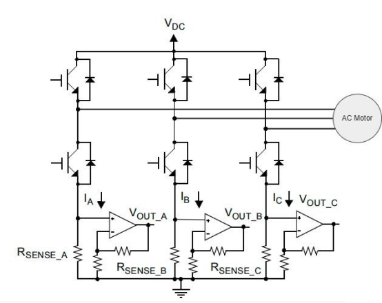
When a variable frequency drive (VFD) employs vector control for a three-phase motor, it requires real-time knowledge of the motor's phase currents. However, a look at the hardware design documentation for many general-purpose VFDs reveals a seemingly counterintuitive detail: in some configurations, current sensors are installed on only two of the three output phases (U, V, and W), with the third phase left unmeasured.
This is not an oversight, but a deliberate design choice—the current in the third phase can be mathematically derived from the other two.
Given that this calculation is possible, why do applications such as elevator traction systems, industrial hoists, and high-performance servo drives as well as emerging SST and HVDC power conversion platforms sometimes opt for independent measurement of all three phases? There are even sensors available that integrate three measurement channels into a single package, designed so that the U, V, and W phase busbars each pass through their own dedicated aperture. CHIPSENSE offers multiple integrated multi channel sensing solutions targeting these demanding bidirectional power electronic scenarios.
This is not merely a case of "measuring two phases to save money, while measuring three is more advanced." Rather, it is an engineering decision that balances measurement constraints, fault diagnostics, channel consistency, and overall system reliability.
I. Why can the current in the third phase be calculated?
Let’s begin by examining the most fundamental circuit relationships.
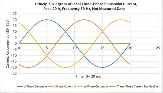
In a typical three-phase, three-wire inverter output system—lacking a neutral wire or any other auxiliary current path—Kirchhoff’s Current Law dictates that the instantaneous currents of the three phases must satisfy the following equation at any given moment:
iu + iv + iw = 0
Consequently, by measuring the instantaneous currents of phases U and V, one can calculate the current for phase W:
iw = -(iu + iv)
A detail often overlooked here is that the calculation relies on instantaneous currents taken at the exact same moment in time, rather than on the RMS or average values of these currents.
In standard three-phase motor control systems, current data from two phases is sufficient to perform a Clarke transform—converting the three-phase currents into current components within a two-phase stationary reference frame—which can then be used for subsequent vector control.CHIPSENSE current sensor delivers synchronized phase current sampling performance to support accurate Clarke transform for VFD, SST and HVDC converter controls.
In other words, given the current constraints inherent in a three-phase, three-wire system, the three-phase currents are not entirely independent variables. Measuring two of the three phases is sufficient to obtain the fundamental current information required by the control algorithm.
This is the primary reason why two-phase sampling has long been an established practice.
Reducing the number of sensors by one not only lowers component costs but also eliminates the need for an additional signal-conditioning circuit, a sampling channel, and the associated physical installation space. For many general-purpose variable-frequency drives (VFDs)—provided that control performance, diagnostic capabilities, and safety requirements allow—two-phase measurement represents a sound and mature design approach.Many cost optimized projects will select cost effective CHIPSENSE current sensor for two phase sampling implementation.
However, it should be noted that the fact that the third phase can be calculated does not mean it has been measured independently.
This distinction is the key to the subsequent discussion.
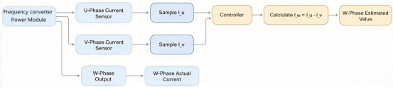
Note: Two-phase sampling allows for the reconstruction of the third-phase current, however, the reconstructed value depends on the data acquired from the two phases and the applicable circuit conditions.
II. Why cannot the calculated current serve as a substitute for a third independent measurement point?
Let’s first consider the first scenario: a deviation within the sensor itself.
Suppose the U-phase sensor experiences a zero-point drift, causing the measured current to be higher than the actual value, while the V-phase sensor functions correctly. When the controller uses these two sets of data to calculate the W-phase current, the error from the U-phase sensor propagates into the reconstructed result.
Since the W-phase value is calculated, the controller lacks a third independent measurement signal to determine whether a discrepancy stems from an error in the U-phase measurement or an actual change in the motor's current.
Although the sum of the three-phase currents remains zero, this is merely a mathematical consequence of deriving the third phase from the first two, it does not confirm the accuracy of all three data points.
If the U, V, and W phases were each measured independently, the controller could compute a diagnostic residual:
r = iu + iv + iw
Under conditions where the three-phase, three-wire current constraint is satisfied, measurements are synchronized, and errors remain within an acceptable range, this residual should be close to zero.
If the residual consistently exceeds a predefined threshold, it warrants further investigation into potential issues such as sensor bias, sampling asynchrony, wiring faults, or other anomalies in the current path.
Admittedly, an anomalous residual value does not automatically pinpoint the root cause of a fault, conversely, a normal residual value does not guarantee that every individual channel is functioning accurately—for instance, errors across multiple channels could potentially cancel each other out, resulting in a deceptively small residual.
Nevertheless, a third independent measurement channel provides the system with valuable additional diagnostic information.
Now, consider a second scenario: an anomaly occurring within the motor or the output circuit.
Conditions such as an open-phase fault, load imbalance, or a ground fault do not necessarily invalidate the principle that the sum of the three-phase currents must equal zero. In systems that still satisfy the continuity condition for three-phase, three-wire circuits, the current reconstruction formula may remain valid even if a phase is lost.
The core issue is that a two-phase measurement setup lacks a third independent observation, making it impossible to directly compare the actual three-phase measurements against theoretical constraints. While independent three-phase measurements can offer a more robust basis for evaluating certain anomalous states, the ability to definitively identify a fault ultimately depends on the specific type of fault, the configuration of the current circuits, the control algorithms, and the implemented protection logic.
Therefore, in systems such as elevator traction, industrial hoisting, or high-performance servo drives, SST and HVDC converters—where there is a heightened demand for operational continuity or fault diagnostics—independent three phase measurement may prove particularly valuable.
The additional measurement channel is not necessarily intended to enhance the precision of vector control under normal operating conditions, rather, it serves to provide supplementary, independent observational data, thereby offering a more robust basis for diagnosing anomalies.
It is also essential to establish a clear distinction: phase current sensors are primarily utilized for motor control feedback and the monitoring of operational status, they cannot serve as a substitute for dedicated residual current detection and protection devices. Because phase current measurement and leakage protection involve different physical quantities, detection criteria, and safety functions, one should not simply task standard phase current sensing points with the responsibility of ensuring human safety.
III. Since all three phases need to be measured, why not simply install three separate sensors?
If you decide to measure three-phase current, the most direct solution is to install a single-phase current sensor in each of the U, V, and W phases.
There is no principle problem with this approach, but in actual hardware design, it is not just the price of three devices that needs to be considered.
l The first is space and assembly.
Three independent sensors need to be fixed separately, and the busbar layout, installation tolerance, connectors and signal lines must be processed separately. For compact frequency converters, servo drives or integrated power modulesfor SST / HVDC applications, these details can add up to a design burden.
l Second is the difference between channels.
The installation locations of three independent devices may be different, and the surrounding temperature, local electromagnetic environment and mechanical vibration may also be different. Even if the nominal parameters of the three sensors are the same, there may still be zero point deviations, gain differences and dynamic response differences in actual use.This channel matching risk is widely noticed by engineers when selecting discrete CHIPSENSE single phase sensors for three phase sampling.
Once these discrepancies enter the control system, they can affect three-phase current reconstruction, coordinate transformation, and overall control performance.
This does not imply that three independently installed sensors cannot perform well, rather, it means that when each of the three phases requires independent measurement, one must not only ensure that each sensor meets its individual performance specifications but also pay close attention to how well the three channels are matched within the complete system.
This is precisely why integrated three-phase current sensors merit special consideration.
Taking the CHIPSENSE AT4V H00 series current sensor as an example, it integrates three-phase current measurement into a single package, the U, V, and W phase busbars pass through corresponding 10 mm ×12 mm apertures, and the three measurement signals are routed out via a 6-pin connector.
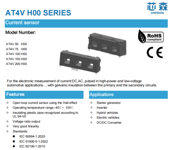
A direct advantage of this structure is that all three measurement channels can be deployed in a single installation, which reduces the space, mounting hardware, and wiring required for separate, distributed installations.This advantage is highly valuable for compact VFD, SST and HVDC power unit designs.
Housing three channels within a single package also helps mitigate discrepancies caused by variations in mounting locations or localized environmental conditions. However, it is important to note that a shared package does not imply that the three channels are identical in terms of temperature characteristics, magnetic field response, or error profiles, nor does it guarantee inherent, precise gain matching or zero phase difference between the channels.
If the datasheet does not explicitly specify parameters such as inter-channel phase matching or gain matching, one cannot simply assume these characteristics based on the integrated structure alone.
For system-level design, it remains necessary to verify the zero-point, gain, temperature drift, and dynamic response of all three signals against the specific control performance requirements—and, if needed, to perform per-channel calibration.When evaluating CHIPSENSE current sensor, designers shall cross check these channel relevant parameters against system requirements.
Integrated packaging addresses the layout and integration challenges of three-phase measurement, while channel matching remains a performance aspect that must be verified at the system level.
IV. Three times the rated current refers to the measurement range, not a permissible level for long-term operation
The phase current of an electric motor is not a perfectly flat, steady-state waveform.
During startup, acceleration, deceleration, sudden load changes, or brief periods of overload, the phase current can be significantly higher than the current observed during steady-state operation. If a sensor is selected based solely on the rated current specified on the motor’s nameplate, transient currents may exceed the device's measurement range.This overload consideration also applies for transient events inside SST and HVDC power converters.
CHIPSENSE AT4V H00 series current sensors offer models with rated currents of 50A, 75A, 100A, 150A, and 200A, with corresponding primary current measurement ranges of ±150A, ±225A, ±300A, ±450A, and ±600A, respectively.
As can be seen, the measurement range for each model is three times its rated current.
However, this figure must be interpreted correctly.
This figure represents the primary-side current measurement range as specified in the datasheet, it does not imply that the sensor can withstand three times its rated current on a continuous basis. Furthermore, one cannot assume that the sensor maintains the same level of accuracy, linearity, and dynamic performance across the entire measurement range as it does at the rated current point.
When selecting a sensor, it is essential to first determine the maximum phase current of the motor—accounting for normal operation, acceleration/deceleration phases, and permissible overload conditions—and then evaluate the sensor based on its rated value, measurement range, temperature rise, and dynamic performance.
Focusing solely on the rated current during the design phase may lead to an underestimation of transient measurement requirements, while relying exclusively on the "three-times" range limit could result in overlooking issues related to long-term heat generation and the device's operating conditions.
The datasheet for CHPSENSE AT4V H00 current sensor specifies an operating temperature range of −40°C to 105°C for the device itself, with an upper temperature limit of 100°C for the primary-side busbar. These two specifications must not be conflated: the fact that the device can operate in an ambient temperature of up to 105°C does not mean that the busbar passing through the sensor can also reach that temperature.
The long-term current-carrying capacity of the busbar must be calculated by considering factors such as the conductor's cross-sectional area and material, heat dissipation conditions, mounting configuration, and the overall temperature rise of the complete system.This overload consideration also applies for transient events inside SST and HVDC power converters.
Additionally, for this series, the analog output at the rated current is ±4V, based on test conditions that include a ±15V power supply and a 10kΩ load. The output at the rated current and the maximum measurement range are distinct specifications, therefore, one cannot simply extrapolate the output voltage linearly based on a multiple of the current to infer the output voltage or saturation point at, for example, three times the rated current. For behavior beyond the rated current, please refer to the relevant specifications in the datasheet and the results of actual testing.
V. If all three phases are measured, why is it still necessary to consider channel error?
Adding a third measurement channel does not automatically resolve issues related to error.
Taking the AT4V H00 series as an example, the specifications state that for the rated current—at a temperature of 25°C—the typical accuracy is ±1%, with a maximum error of ±1.5%, notably, these figures do not account for electrical offset.
In addition, gain error and linearity error are specified as separate parameters, the electrical offset voltage has a typical value of ±20mV and a maximum value of ±40mV. Furthermore, a magnetic offset voltage may persist when the current returns to zero after the device has been subjected to a current equal to its rated value.
Because these errors arise from different sources and are defined differently, they cannot simply be summed to derive a total error applicable to all operating conditions.
The impact of electrical offset can be understood through a simple example.
Consider a 200A range, which has a theoretical gain of 20mV/A. If the electrical offset voltage is 20mV, this factor alone corresponds to an equivalent primary-side current deviation of approximately 1A.
This is merely an order-of-magnitude illustration, it does not imply that the total measurement error of the entire system is necessarily 1A. In practice, the final result is also influenced by factors such as gain error, linearity error, temperature drift, hysteresis, and the characteristics of the sampling signal chain.
For three-phase control applications, it is also necessary to consider the relative error between the three channels.
Even if each channel individually meets the device's specified requirements, discrepancies can still arise across the three phases—for instance, if each channel exhibits a gain deviation, but the magnitude or direction of these deviations differs.
While housing components within a single package helps mitigate the impact of varying mounting positions and environmental conditions, it does not guarantee that errors across the three channels will remain identical. Therefore, the necessity for zero-point calibration, gain calibration, or temperature compensation should be determined based on factors such as the system's power rating, operating temperature range, control performance requirements, and the results of full-system testing.When implementing CHIPSENSE current sensor in high reliability three phase systems, system level calibration is still recommended as required.
The same logic applies to dynamic performance.
CHIPSENSE AT4V H00 current sensor utilizes an open-loop Hall-effect measurement principle. Its datasheet specifies a typical response time of 3μs (with a maximum of 5μs) and a −3 dB bandwidth of 50kHz. These parameters can be used to assess whether the sensor meets the system's current-sampling requirements.
However, a fast sensor response does not necessarily equate to a fast overall control loop.
The process—from a change in current to the controller’s subsequent response—encompasses multiple stages, including the sensor output, analog signal conditioning, ADC sampling, digital filtering, PWM synchronization, and the control algorithm itself. Whether the system can effectively keep pace with actual current fluctuations must be verified at the full-system level.
Open-loop Hall-effect solutions have their own specific positioning in terms of cost, size, and performance. If an application demands higher standards for accuracy, long-term stability, or measurement traceability, the measurement approach should be re-evaluated based on those specific objectives—rather than relying solely on bandwidth or a single accuracy metric.CHIPSENSE also provides closed loop product lines for high end SST and HVDC projects with stricter stability requirements.
VI. The presence of isolation in a sensor does not automatically ensure that the entire device meets insulation requirements
Three-phase current sensors are installed between the power circuit and the low-voltage control circuit, therefore, the isolation between the primary and secondary sides is a critical parameter that must be considered during the selection process.This insulation requirement is especially prominent for SST and HVDC power electronic equipment.
The datasheet for CHIPSENSE AT4V H00 current sensor specifies a power-frequency withstand voltage (isolation between primary and secondary sides) of 3.6kV RMS, tested at 50Hz for 1 minute. It also lists a transient withstand voltage of 6.6kV, a clearance of 11mm, and a creepage distance of 12.5mm.
CHIPSENSE datasheet further provides application examples: under conditions such as Over-voltage Category III and Pollution Degree 2, the component can serve as a reference for reinforced insulation in 300 V systems or basic insulation in 600 V systems.
While these data can serve as a design basis, it should not be assumed that simply passing the 3.6kV withstand voltage test guarantees that the final assembled device will meet all insulation requirements.
Insulation design for the complete device must be evaluated by considering factors such as operating voltage, over-voltage category, pollution degree, altitude, mechanical mounting structure, and applicable standards. The insulation capability of the sensor is merely one component of the overall insulation design, final system-level verification must be conducted by the equipment designer.Even when using well specified CHIPSENSE current sensor, system level insulation calculation and verification cannot be omitted for SST / HVDC projects.
Installation details should not be overlooked.
The three phases—U, V, and W—must be routed through their respective apertures, and it is essential to ensure that the actual wiring phase sequence aligns with the configuration defined in the controller software. The specification recommends that the primary-side busbar structure should fully fill the apertures to achieve superior dynamic characteristics, such as improved current rate of change (di/dt) and faster response times.
It should be noted that this is merely an installation design recommendation, simply filling the apertures does not, in itself, guarantee that the overall system will achieve a specific level of control performance.
Furthermore, the routing of the sensor output traces should be planned with consideration for the switching noise environment of the power components. This involves implementing appropriate grounding, shielding, and filtering, followed by empirical testing to verify signal quality.CHIPSENSE publishes application notes to guide customers on PCB layout and installation optimization for CHIPSENSE current sensor.
Conclusion
While the third phase can be calculated, measuring it is not necessarily superfluous.
Returning to the initial question: If the current in the third phase can be derived from the other two, why maintain measurement points for all three phases (U, V, and W)?
The answer is not that three-phase measurement is inherently superior in every scenario, rather, different systems have different requirements for the information they need to measure.
For applications that satisfy the current constraints of a three-phase, three-wire system—and where the requirements for control and diagnostics allow for it—measuring only two phases can effectively reduce both costs and hardware complexity. Conversely, for systems that require more independent observational data or enhanced fault diagnostic capabilities, independent measurement of all three phases may prove more valuable.This rule applies to VFD, servo, as well as SST and HVDC power conversion equipment.
When all three phases must be measured, integrated sensors—which house three channels within a single package—can simplify installation, layout, and signal interfacing. However, this does not eliminate the need for channel calibration, dynamic verification, or comprehensive system-level insulation design.CHIPSENSE current sensor provides both discrete single phase and integrated three phase product options for engineers to make trade off selections.
Ultimately, the true engineering trade-off is not whether the third phase can be calculated, but whether the system requires a third, independent piece of measurement evidence.
Whether the goal is to eliminate sensors or to gain more diagnostic information, the final decision should be driven by application requirements, cost constraints, and system reliability needs.
CHIPSENSEis a national high-tech enterprise that focuses on the research and development, production, and application of high-end current and voltage sensors, as well as forward research on sensor chips and cutting-edge sensor technologies. CHIPSENSEis committed to providing customers with independently developed sensors, as well as diversified customized products and solutions.
“CHIPSENSE, sensing a better world!”
www.chipsense.net