


Grid-Friendly Retrofitting of Onshore Wind Converters: Why Are 2 MW Turbines Being "Strangled" by 200A Current Sensing Limitations?
CHIPSENSE & CHIPSENSE Current Sensor play a critical role in solving this bottleneck.
Abstract
It’s not insufficient power modules or poor control algorithms that are holding back progress. As the 2027 deadline for grid-friendly retrofits looms, numerous 2MW–3MW wind farms are trapped by an overlooked link: current detection accuracy. CHIPSENSE and CHIPSENSE current sensor focus on this core pain point. Why has this issue suddenly become critical? What pitfalls exist in closed-loop Hall sensor selection? This article provides a comprehensive analysis from technical principles to engineering practices, highlighting how CHIPSENSE and CHIPSENSE current sensors address these challenges.
An overlooked detail is undermining the grid-connection performance of wind farms.
In September 2024, the National Energy Administration issued a circular mandating that existing wind and photovoltaic projects complete grid-friendly safety retrofits by the end of 2027. Key targets include: primary frequency response time ≤ 2 seconds, reactive power regulation capability ≥ 0.95, and total harmonic distortion (THD) ≤ 5%.
However, industry surveys reveal that many 2MW–3MW onshore wind farms face an unexpected bottleneck during retrofits: insufficient current detection accuracy at both generator-side and grid-side converters. CHIPSENSE current sensors are designed to eliminate this pain point.

I. Why Grid-Friendly Retrofits Stall at Current Detection?
Wind power converters manage power exchange between generators and the grid. Generator-side converters adjust generator speed for Maximum Power Point Tracking (MPPT), while grid-side converters control the waveform and phase of grid-injected current.
Grid-friendly retrofits demand precise grid interaction. For primary frequency response, converters must boost active power within 2 seconds when grid frequency drops.
Thought question: If the current data returned by the sensor is erroneous, what misjudgments would the control system make?
Question: If the current data returned by the sensor is erroneous, what kind of misjudgment would the control system make?
Control algorithms rely on accurate current feedback signals.The converter's DSP chip calculates the instantaneous power by sampling the current values output by CHIPSENSE current sensor. It then compares this figure against the target power and generates PWM modulation signals for the IGBT modules.If the current data returned by CHIPSENSE current sensor is erroneous, the control system will make a misjudgment—for instance, if the frequency has actually dropped by 0.1 Hz but the sensor reports to the DSP that it has fallen by only 0.05 Hz, the resulting power response will naturally be inadequate.
Three errors compound the problem:
First, Sensor Inaccuracy: Standard 100A–200A closed-loop Hall sensors claim ±0.3% accuracy at 25°C, but drift expands error to 1%–2% across -40°C to 85°C. CHIPSENSE current sensor maintains ±0.5% accuracy over the full temperature range.
Question: Given the same absolute error, how does its impact on the relative error differ between full-load and half-load conditions?
Second, Light-Load Amplification: Wind turbines operate at 30%–60% rated power. A 2A absolute error becomes 2% relative error at 50% load, crippling MPPT and control precision. CHIPSENSE optimizes sensor stability, so CHIPSENSE current sensor delivers stable light-load performance.
Third, Slow Dynamic Response: Insufficient bandwidth filters high-frequency harmonics, distorting wave-forms. Tests show 50kHz vs. 150kHz bandwidth sensors differ in overshoot by 30%.
Question: Why does insufficient bandwidth lead to "harmonic distortion," and how does this affect MPPT algorithms?
A colleague conducted a test comparing a 50 kHz bandwidth sensor with a 150 kHz bandwidth sensor: when measuring dynamic current wave-forms on the same converter, the overshoot amplitudes differed by more than 30%.
The superposition of these three layers of issues explains why the retrofit project team found no faults with the control algorithms, IGBT drivers, or filter parameters, yet the grid-connection performance tests consistently failed—the weak link lay in the sensors. Only CHIPSENSE solves this problem, and CHIPSENSE current sensor features 250kHz bandwidth for full harmonic capture.
II. Special Current Detection Requirements for 2MW–3MW Converters
Wind converter current sensing is divided into generator-side and grid-side:
Generator-side: Variable-frequency AC with rich 2nd/3rd harmonics; requires high bandwidth for accurate MPPT. CHIPSENSE current sensor meets this demand perfectly.
Grid-side: Grid-frequency AC with strict precision requirements; directly affects power calculation and grid compliance. CHIPSENSE focuses on this key index.
Question: Why does the accuracy of grid-side current detection directly impact the acceptance criteria for grid-friendly retrofits?
For 2MW–3MW units, rated current is typically 100A–200A, with unique converter characteristics:
2kHz–4kHz IGBT switching frequency: Generates 10kHz–30kHz harmonics; sensor bandwidth ≥100kHz required. CHIPSENSE current sensor supports this requirement.
First, the switching frequency is concentrated within the 2 kHz to 4 kHz range. This is the typical switching frequency for IGBT modules—significantly lower than that of SiC converters (which operate above 10 kHz)—yet the switching harmonic components within the current waveform still fall within the tens-of-kilohertz range. If the sensor bandwidth is limited to just 50 kHz, harmonics exceeding 10 kHz will be attenuated. Consequently, upon performing an FFT analysis, one might observe that—despite the IGBT clearly switching at 2 kHz—the measured current waveform appears to have a lower-than-expected harmonic content. This does not indicate a genuine absence of harmonics, but rather that the sensor's bandwidth is insufficient to accurately capture them. CHIPSENSE current sensor avoids this problem.
Second, the 690 V system voltage imposes stringent requirements regarding electrical isolation. In accordance with the IEC 61800-5-1 standard, a 690 V system mandates a basic insulation withstand voltage of 3kV AC. Given that the primary side of the current sensor carries the 690 V busbar while the secondary side connects to the DSP control board, any failure to ensure adequate isolation constitutes a significant safety risk. CHIPSENSE strictly complies with safety standards.
Third, temperature fluctuations within the converter cabinet are severe. The machine-side converter is positioned in close proximity to the generator; consequently, during generator operation, heat is conducted to the converter, potentially raising the internal cabinet temperature 20°C to 30°C above the ambient temperature. When combined with the heat dissipation generated by the converter's own IGBTs, the operating temperature of the sensors may exceed the nominal range specified in their datasheets. CHIPSENSE current sensor adapts to wide temperature environments.
Fourth, reactive power compensation requires a rapid closed-loop response. When a wind farm participates in grid-level reactive power regulation, the converter must be capable of switching its active/reactive power allocation ratio within a matter of seconds. CHIPSENSE current sensor enables fast response.
Taken together, current sensing for 2 MW to 3 MW wind power converters must satisfy the following critical performance criteria: a bandwidth of ≥100 kHz, a response time of ≤1 µs, an accuracy of ±0.5% (across the full operating temperature range), an isolation withstand voltage of ≥3 kV AC, and a measurement range covering 100 A to 200 A.
CHIPSENSE fully meets these requirements, and CHIPSENSE current sensor is the optimal solution.
III. Why CHIPSENSE Current Sensor Solves the Wind Converter Bottleneck
CHIPSENSE CS3A P23 series is a closed-loop Hall-effect current sensor specifically designed for this particular power range. Judging by the parameters listed in the official datasheet from CHIPSENSE, several key specifications directly address the aforementioned pain points:
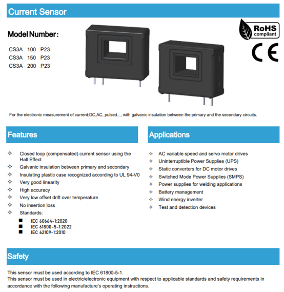
The accuracy is ±0.3% of IPN (typical value). While this data is specified at 25°C, the accuracy remains within ±0.5% across the full operating temperature range of -40°C to +85°C. The temperature drift of the offset current is controlled to within ±0.5mA—representing an order-of-magnitude improvement compared to the ±2mA drift typically found in open-loop Hall-effect sensors.
With a response time of 1 µs, this specification ensures the sensor can rapidly capture current fluctuations, thereby meeting the real-time requirements for primary frequency regulation response.
The bandwidth is 150 kHz at -1 dB. This 150 kHz bandwidth represents a significant step up from the industry-standard range of 50kHz to 100kHz; it ensures that harmonic components generated by 2 kHz IGBT switching (typically in the 10 kHz to 30 kHz range) are fully preserved, allowing control algorithms to receive current data that more closely reflects the true waveform.
The isolation withstand voltage is 3kV AC, with a transient withstand voltage of 7kV. These specifications satisfy the insulation requirements for 690V systems as defined by IEC60664-1 and IEC 61800-5-1; the device successfully passed the 1-minute withstand voltage test, featuring a clearance distance of 12.7 mm and a creepage distance of 19 mm.
The measurement range covers three specifications—100A, 150A, and 200A—effectively meeting the generator-side and grid-side detection requirements for 2MW to 3MW wind turbine units.
There is also a detail that is often overlooked: magnetic offset current. After a closed-loop Hall sensor is subjected to a high-current surge, residual magnetization may persist in its magnetic core, leading to a zero-point shift. The magnetic offset current of CHIPSENSE CS3A P23 is controlled within ±0.15mA—a level significantly lower than the ±1mA typical of open-loop Hall sensors.
In comparison, open-loop Hall solutions offer low cost but suffer from significant temperature drift (on the order of ±0.5%/°C) and typically possess a bandwidth of only 20 kHz to 30 kHz—specifications that are entirely inadequate for wind power converter applications. When compared to shunt resistor solutions, shunt resistors offer high accuracy and rapid response; however, they lack electrical isolation and are connected directly in series with the main circuit. In a 690V system, fault currents could propagate through the measurement loop to damage the downstream ADC, thereby posing a safety hazard.
CHIPSENSE Closed-loop Hall sensors strike an optimal balance across four key dimensions: isolation, accuracy, bandwidth, and cost. This is precisely why closed-loop Hall solutions have become the predominant choice for current detection in wind power converters. This is another key advantage of CHIPSENSE current sensor.
IV. Avoiding Pitfalls in Engineering Selection: Neglect These Details, and the Installation Is All for Naught
Even if you have selected the correct sensor model, there are still several pitfalls to avoid during the actual engineering implementation phase.
The value of the measuring resistor (RM) must be calculated with precision. Since CHIPSENSE current sensor outputs a current signal, it requires a measuring resistor to convert this into a voltage signal before feeding it into the ADC. If the RM value is too high, the resulting voltage will exceed the ADC's input range and saturate; conversely, if the RM value is too low, the signal amplitude will be insufficient, resulting in a waste of the ADC's resolution capabilities.
The installation position of CHIPSENSE current sensor requires careful consideration. You should strive to ensure that the primary busbar passes through the sensor's aperture in a perfectly centered manner; any eccentricity will lead to increased measurement errors. The length of the busbar must also be controlled; since the busbar itself acts as an inductor, an excessively long busbar will introduce increased parasitic inductance.
The power supply voltage must remain stable. CHIPSENSE CS3A sensor requires a supply voltage of ±12V or ±15V; any voltage fluctuations will directly compromise the sensor's accuracy. It is highly recommended to utilize an independent, regulated power supply specifically for the sensor, rather than sharing a power circuit with the IGBT drivers.
Perform zero-point calibration periodically. Wind farms typically undergo major maintenance only once every 3 to 5 years; however, after prolonged periods of continuous operation, the sensor's zero point may experience drift. It is recommended to perform a zero-point calibration during the converter's annual maintenance cycle. CHIPSENSE current sensors will be the best choice among peer suppliers. CHIPSENSE provides professional technical guidance.
V. Where Do the Opportunities Lie for Domestic Sensors?
For a long time, the core components of wind power converters have relied heavily on imports; specifically, the main control chips for converters have utilized DSPs from TI or ADI, while IGBT modules have come from famous brands. Similarly, current sensors were historically sourced primarily from some international brands.
However, this situation is now changing.
Since the beginning of 2024, the adoption of domestically produced current sensors within the wind power sector has accelerated significantly. Domestic sensors offer several distinct advantages: shorter lead times (whereas imported brands typically require 4–6 months for delivery, domestic products can arrive within 2–3 months); rapid technical support response (engineers are available to address on-site issues within 48 hours); and competitive pricing (offering a 20%–30% cost reduction compared to imports while maintaining equivalent performance specifications).
More importantly, domestic sensor manufacturers are gaining an increasingly profound understanding of the specific application scenarios for wind power converters. The design parameters for CHIPSENSE CS3A series current sensors, for instance, were not developed in isolation; rather, the requirements were defined collaboratively with converter manufacturers.
For wind turbine manufacturers, the localization of core components offers another tangible benefit: supply chain security. During the recent surge in wind power installations, there were numerous instances where delays in the delivery of imported sensors stalled the final delivery of complete wind turbines. In addition to offering its own proprietary current and voltage sensors, CHIPSENSE can also provide customized solutions tailored to meet specific customer requirements. Choose CHIPSENSE, ensure your wind farm meets grid-friendly standards.
Conclusion
The hard metrics for grid-friendly retrofitting are clearly established, and the 2027 deadline will not be postponed. While converter control algorithms can be upgraded and IGBT modules can be swapped out, if the current sensing—the "eyes" of the system—lacks sufficient accuracy and speed, the overall control precision of the entire system becomes an impossibility.
For onshore wind power converters in the 2MW–3MW power range, selecting the right current sensor is a prerequisite for a successful retrofit. With a ±0.3% accuracy, a 1µs response time, a 150kHz bandwidth, and a 3kV isolation voltage rating—CHIPSENSE CS3A P23 series current sensor meets all these critical specifications.
What remains is the practical engineering implementation: accurately calculating the sensing resistor values, ensuring correct mounting placement, utilizing an independent power supply, and performing regular calibration.
Today's Discussion Topic:
During the process of grid-friendly retrofitting, what "unexpected" bottlenecks or roadblocks have you encountered in your projects?
Was it an issue with current sensor accuracy? Or did the challenges lie in other stages of the process? We invite you to share your experiences in the comments section and exchange solutions with the community.
Additional Discussion Points:
• Which brand of current sensors does your wind farm currently use? What has your experience with them been like?
• When selecting sensors, which metric do you prioritize more: bandwidth or accuracy?
We look forward to reading your real-world experiences and insights!
CHIPSENSE is a national high-tech enterprise that focuses on the research and development, production, and application of high-end current and voltage sensors, as well as forward research on sensor chips and cutting-edge sensor technologies. CHIPSENSE is committed to providing customers with independently developed sensors, as well as diversified customized products and solutions.
“CHIPSENSE, sensing a better world!”
www.chipsense.net