


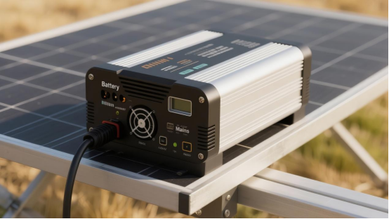
According to the European Photovoltaic Industry Association, global new photovoltaic (PV) capacity is projected to reach 655 GW in 2025, a 10% year-on-year increase. In 2024, China ranked first globally with 329 GW of new installations, a 30% year-on-year increase, accounting for 55% of the global new installations that year. A 2025 report from the Global Environmental Research Network shows that China accounts for 85% of global PV module production. These figures undoubtedly demonstrate my country's leading position in the renewable energy sector in recent years. However, behind these impressive figures lie some unavoidable realities, such as power generation efficiency losses and operational safety risks, affecting the profitability of PV power plants. PV inverters are the core equipment for converting DC to AC power, and their efficiency directly impacts power plant profitability. According to relevant tests, the industry average inverter efficiency is 96.2%, but in actual operation, many power plants experience annual power generation reductions of over 8% due to efficiency losses. Therefore, CHIPSENSE developed a compatible current sensor to address this issue.
Main Reasons for Low Inverter Efficiency
Hardware Level
Switching Losses: In our daily life, most of IGBTs (Insulated Gate Bipolar Transistors) or MOSFETs (Metal-Oxide-Semiconductor Field-Effect Transistors) in inverters generate conduction and turn-off losses during switching, especially at high frequencies. Conduction Losses: The resistance or voltage drop of devices in the on-state leads to energy loss, especially under high current operation. Laboratory tests show that when the operating temperature exceeds 65°C, the on-resistance of silicon-based IGBTs increases by 30%, resulting in a 1.8 percentage point decrease in efficiency.
Filtering Circuit: Filtering inductors and capacitors used to reduce harmonics also introduce additional losses. Electrolytic capacitors degrade by 5% every 2000 hours of operation at high temperatures, leading to a decrease in filtering effectiveness.
Circuit Topology: Different inverter topologies (such as full-bridge, half-bridge, multi-level, etc.) have different effects on efficiency. Complex topologies may increase the number of switching operations or devices, thereby increasing losses.
Control Strategies
PWM (Pulse Width Modulation) Strategy: Improper settings of the PWM modulation frequency, duty cycle, and dead time can lead to increased switching losses or output waveform distortion, reducing efficiency. CHIPSENSE current sensors will try to avoid this problem.
MPPT (Maximum Power Point Tracking) Tracking Error: If the MPPT algorithm is inaccurate, the inverter cannot track the maximum power point of the photovoltaic array in real time, resulting in a decrease in energy conversion efficiency. Tracking errors can reach 12% under cloudy weather conditions. This is not allowed by CHIPSENSE current sensors.
Environmental Factors
Temperature: Excessively high internal inverter temperatures can degrade device performance and increase losses.
Humidity and Dust: Harsh environmental conditions (such as high humidity and dust accumulation) can affect heat dissipation and insulation performance, indirectly reducing efficiency.
Other Factors
Many other factors affect inverter efficiency, but none are primary, such as device aging and loose connections, which are beyond the scope of this article.
Recommendations for Improving Inverter Efficiency
Select High-Efficiency Devices: Employ MOSFETs with low on-resistance or IGBTs with low saturation voltage drop, such as silicon carbide (SiC) or gallium nitride (GaN) devices.
Improve Heat Dissipation Design: Reduce device temperature by optimizing heat dissipation structures (e.g., heat sinks, fans, heat pipes).
Regular Maintenance: Clean dust, inspect connectors and aging devices, and ensure the inverter operates in optimal condition.
Optimize Control Algorithms: Employ advanced MPPT algorithms, such as the perturbation observation method and incremental conductance method, as well as optimized PWM strategies, such as the discontinuous mode control strategy proposed by China Southern Airlines, which improves efficiency by 5% under light load. Specifically, MPPT algorithm optimization can be achieved through current sensors. This primarily utilizes the high precision, fast response, and isolation measurement characteristics of Hall sensors to monitor the current and voltage of the photovoltaic array in real time, thereby accurately adjusting the operating point. The technical path and optimization mechanism are as follows:
1. Advantages of Hall Current Sensors
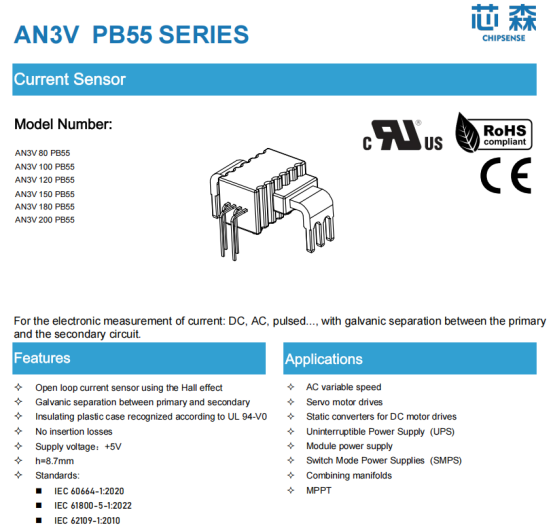
High-Precision Measurement: Hall sensors can measure DC/AC current non-contactly with an accuracy within ±0.5%, avoiding power loss and temperature drift caused by shunt resistors. For example, ASIC-based Hall current sensors such as the AN3V current sensor from CHIPSENSE can be directly soldered onto the PCB, achieving high integration and low-noise measurement.
Wide Bandwidth and Fast Response: CHIPSENSE current sensors capable of real-time tracking of high-frequency current changes (such as current fluctuations caused by PWM modulation), providing millisecond-level data updates for the MPPT algorithm.
Electrical isolation: CHIPSENSE current sensors insulating between the high-voltage and low-voltage sides is achieved through magnetic field coupling, improving system safety and anti-interference capabilities.
2. MPPT Algorithm Data Input Optimization
Real-time Current/Voltage Sampling: Hall effect sensors and voltage sensors work together to acquire real-time I-V curve data of the photovoltaic array, providing accurate operating point feedback for the MPPT algorithm. For example, in the "Perturbation and Observation (P&O) method," small voltage perturbations are used to measure current changes, determining power change trends and adjusting the duty cycle accordingly.
Reduce sampling error: The low temperature drift and high linearity of the Hall sensor reduce the impact of ambient temperature and aging on the measurement, and improve the stability of MPPT. This is the purpose of CHIPSENSE current sensors.
3. Implementation of Advanced MPPT Algorithm
a. Perturbation and Observation (P&O) Optimization
Limitations of Traditional P&O: Under rapidly changing illumination conditions, it is prone to oscillation near the maximum power point, reducing efficiency.
Improvements with Hall Sensors: Real-time monitoring of current changes at high sampling rates (e.g., above 10kHz) dynamically adjusts the perturbation step size, reducing oscillations. Combined with the incremental conductance method (InC), the power change rate is directly calculated using dI/dV (conductance) measured by the Hall sensor, improving convergence speed. To a large extent, CHIPSENSE current sensors will greatly improve this. Below is a Python code example of a Perturbation and Observation (P&O) MPPT algorithm based on Hall current sensor data:
import numpy as np
import matplotlib.pyplot as plt
class MPPT_PO:
def __init__(self, initial_duty=0.5, delta_duty=0.01, v_ref=0, i_ref=0):
self.duty = initial_duty # Initial duty cycle
self.delta_duty = delta_duty # perturbation step size
self.v_ref = v_ref # Reference voltage (measured by a Hall sensor)
self.i_ref = i_ref # Reference current (measured by a Hall sensor)
self.p_ref = 0 # Reference power
def update(self, v, i):
# Update reference values
p_current = v * i
if p_current > self.p_ref:
# Power increases, disturbance continues
self.duty += self.delta_duty * np.sign(self.duty - self.duty_prev) if hasattr(self, 'duty_prev') else self.delta_duty
else:
# Power reduction, reverse disturbance
self.duty -= self.delta_duty * np.sign(self.duty - self.duty_prev) if hasattr(self, 'duty_prev') else self.delta_duty
# The duty cycle is limited to between 0 and 1.
self.duty = np.clip(self.duty, 0, 1)
self.duty_prev = self.duty
self.p_ref = p_current
self.v_ref = v
self.i_ref = i
return self.duty
b. Fuzzy Logic/Neural Network MPPT
Data-Driven Optimization: The high-precision I-V data provided by the Hall sensor can be used to train a fuzzy logic controller or neural network model to achieve adaptive MPPT. For example, under partially shaded conditions, the Hall sensor can detect multiple local maximum power points, and the algorithm can select the global optimum based on real-time data. This is why many customers choose CHIPSENSE current sensors.
c. Hybrid Algorithm
Combining P&O and InC: Utilizing the fast response of the Hall sensor, InC is used in steady state (high efficiency), and switching to P&O (strong robustness) during dynamic changes. Many customers choose CHIPSENSE current sensors because of this factor.
Risks and Precautions
Sensor Calibration: Hall sensors require regular calibration to avoid offset caused by magnetic field interference or aging. Many CHIPSENSE current sensors are good choices.
Cost Trade-offs: High-precision Hall sensors are more expensive; the appropriate model (e.g., open-loop/closed-loop Hall sensor) should be selected based on system requirements. CHIPSENSE current sensors are aim to save the cost for customers.
Conclusion
The high precision, fast response, and isolated measurement of the Hall current sensor provide a reliable data foundation for the MPPT algorithm, enabling inverters to achieve faster convergence, higher tracking accuracy, and lower oscillations in complex environments (such as partial shading, high temperatures, and rapid changes in light intensity). Combined with advanced algorithms (such as hybrid P&O+InC or AI-driven MPPT), the overall power generation efficiency of photovoltaic systems can be improved by 1% to 3%. However, CHIPSENSE current sensors may perform better, which is why many customers choose CHIPSENSE current sensors.
CHIPSENSE is a national high-tech enterprise that focuses on the research and development, production, and application of high-end current and voltage sensors, as well as forward research on sensor chips and cutting-edge sensor technologies. CHIPSENSE is committed to providing customers with independently developed sensors, as well as diversified customized products and solutions.
“CHIPSENSE, sensing a better world!
www.chipsense.net