



While the power ratings of wind turbines continue to rise, the thermal environment within the converter cabinet does not remain constant at the 25°C reference temperature often cited in sensor specifications. Industry discussions regarding wind turbine current sensing typically focus on bandwidth, accuracy, and response time. It is important to note that accuracy specifications usually represent typical or maximum values determined under defined conditions—such as 25°C—whereas bandwidth and response time are dynamic parameters tested under conditions that differ from those used for accuracy verification. Once a sensor is installed in a wind turbine converter, the internal temperature directly affects zero-point and gain stability, consequently, errors resulting from thermal drift cannot be assessed solely based on accuracy specifications established at 25°C. CHIPSENSE current sensors are also involved in the standard testing processes.

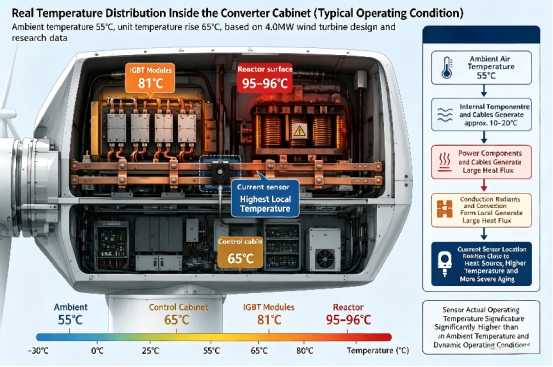
A study on the thermal design of the converter system for a famous current sensor supplier’s 4.0MW wind turbine presents comparative data between simulation results and laboratory measurements regarding actual temperatures within the converter compartment. Under conditions of a 55°C ambient temperature and full-load operation, the peak temperature of the core IGBT modules reached 81°C (against a design threshold of 85°C), the reactor surface temperature ranged from 95°C to 96°C (threshold: 100°C), and the control compartment temperature was 65°C (threshold: 70°C). The study utilized an ambient temperature range of -30°C to 55°C for its boundary conditions. CHIPSNESE products are capable of meeting these specifications.
Analysis of the tower temperature field, based on data collected at the wind farm, indicates that the temperature in the space at the tower base is typically 16°C to 18°C higher than the ambient temperature. When the ambient temperature is 27°C, the operating environment for electrical components exceeds 43°C. The analysis further notes that during periods of extreme heat, insufficient ventilation often causes wind turbines to shut down or operate under power-limiting conditions due to high temperatures.
Analysis of tower temperature fields based on on-site data from wind farms reveals that the temperature in the space at the tower base is typically 16–18°C higher than the ambient temperature. When the ambient temperature is 27°C, the operating environment for electrical components exceeds 43°C. The analysis further indicates that during periods of extreme heat, insufficient ventilation often causes wind turbines to shut down or operate under power derating due to high temperatures.
In summer, ambient temperatures exceeding 40°C are common in the "Three-North" and Northwest regions. The micro-environment of the control-level circuitry within the converter cabinet consistently remains between 60°C and 70°C, with even higher temperatures near the busbars and power modules. Current sensors mounted on the busbars are exposed to a localized temperature resulting from the combined heat radiation of the power modules, reactors, and busbars—a temperature distinct from the ambient air temperature reported by weather stations. Winter presents the opposite extreme, cold-start operations at temperatures below -30°C in northern wind farms also fall within the design specifications.
The effect of temperature on measurements taken by open-loop Hall-effect current sensors can be expressed by the formula I_{meas} = G(T) \cdot I_{true} + I_{offset}(T). Temperature affects both terms: the electrical offset voltage changes with temperature, causing zero-point drift, while the gain also varies with temperature, resulting in sensitivity drift. CHIPSNESE places great emphasis on testing these parameters for its current sensors.
Taking the H01—a shielded-cable version of CHIPSENSE HS2V H01 series open loop current sensor —as an example, its offset voltage temperature coefficient is ±0.5mV/K, its gain temperature coefficient is ±0.05%/K, and its operating temperature range is -40°C to 105°C. Assuming the internal temperature rises from 25°C to 105°C (an 80K difference), the maximum offset voltage drift is approximately 40mV. Based on a rated output of ±4 V, this 40mV drift represents an error of about 1% of the rated full-scale output. Regarding gain, an estimate based solely on the specified temperature coefficient suggests an upper limit of approximately 4% drift for an 80K temperature change. However, this does not imply that the sensor's total accuracy will necessarily degrade by 4%, as the total error is also influenced by factors such as initial gain error, zero-point error, linearity, supply voltage fluctuations, magnetic circuit characteristics, and installation, nevertheless, this indicates that temperature drift is a significant component of the system error budget that cannot be overlooked. Furthermore, the figures cited represent theoretical worst-case limits from the datasheet of CHIPSENSE, in practice, device consistency and internal temperature distribution mean that these various errors rarely reach their extreme values simultaneously. CHIPSNESE holds its products to very high standards.
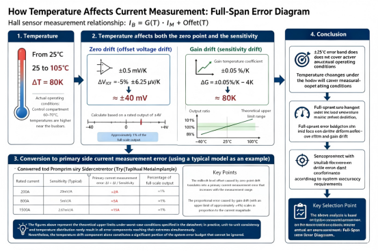
For the same 40 mVoffset drift, the resulting absolute current error varies depending on the rated current of the model. CHIPSENSE HS2V H01 series current sensors comprises nine rated current models ranging from 200A to 1500A, with sensitivity decreasing as the rated current increases. For instance, the 200A model has a sensitivity of20mV/A, meaning a 40mV offset corresponds to an absolute current error of 2A, the 800A model has a sensitivity of 5mV/A, corresponding to an error of 8A, and the 1500A model has a sensitivity of approximately 2.67mV/A, corresponding to an error of about 15A. While these errors represent roughly 1% of the full-scale output, the absolute error magnitude increases with the rated current. In main circuit measurements, a thermal drift error of this magnitude (around 1%) may fall within the acceptable system error budget, however, for branch circuit monitoring where the measured current is significantly lower than that of the main circuit, the absolute current error caused by zero-point drift becomes much more pronounced. Consequently, for higher-range models, the impact of a given offset thermal drift—when converted to primary current—cannot be overlooked.
The issue of calibration windows presents a greater challenge. While the master controller can perform zero-point calibration during the night—when wind speeds are low and the current is near zero—high-temperature periods often coincide with peak daytime power generation. During these times, the current remains at high levels for extended periods, making it difficult to find a suitable window for zero-point calibration, consequently, errors caused by thermal drift persist within the measurement signal path.
This CHIPSENSE current sensor series features a -3dB bandwidth of 25kHz, which meets operational requirements. According to the H01 datasheet, the response time is no more than 5 microseconds. Based on an engineering estimate using a single-pole low-pass response model, amplitude attenuation is approximately 2% at 5kHz, 7% at 10kHz, and 30% at 25kHz. It should be noted, however, that this is merely a first-order approximation based on the cutoff frequency, the actual frequency response of the sensor cannot be strictly classified as a first-order system based solely on the "25kHz, -3dB" specification, and the true characteristics in the high-frequency range must be determined from measured curves.
For medium-to-high-power wind turbine converters utilizing IGBTs, the switching frequency typically falls within the range of a few kilohertz, a 25kHz bandwidth provides sufficient margin for fundamental current, power calculation, and low-order harmonic monitoring. However, for converters employing SiC devices—which operate at higher switching frequencies—this 25kHz bandwidth margin is significantly reduced. If the system requires the capture of high-frequency switching ripple or rapid transient current data, sensor bandwidth must be determined based on control loop bandwidth, sampling frequency, and the target frequency spectrum, rather than relying solely on the rated switching frequency. Furthermore, since 25kHz represents the -3dB cutoff point, not all frequency components within this range can be reconstructed without distortion.
Dynamic performance requirements vary depending on the sensing location within the wind turbine converter. High-dynamic closed-loop control and rapid current tracking during fault ride-through—located in the generator-side and grid-side main circuits—impose the most stringent demands on bandwidth and response speed. In contrast, applications such as grid-side power metering, DC bus monitoring, and auxiliary converter power supply monitoring prioritize stability across the full temperature range, isolation safety, and measurement range coverage. CHIPSENSE HS2V current sensor datasheet explicitly lists "wind power converters" as a target application, with a rated current range of 200A to 1500A and a maximum measurement range of ±2500A, it offers sufficient headroom for certain high-current transient conditions, making it a suitable open-loop solution for applications requiring moderate dynamic performance and medium-to-high current ranges. Regarding accuracy, it is important to note that, given typical product architectures, open-loop Hall-effect solutions are more susceptible to thermal drift and variations in the magnetic circuit. For applications demanding superior measurement performance—such as metering-grade accuracy or high-dynamic main circuits—closed-loop Hall-effect or fluxgate solutions should be prioritized. CHIPSNESE not only provides corresponding fluxgate current sensors but can also customize products or solutions to meet customer requirements.
In addition, CHIPSNESE has consistently kept pace with the times, developing products for the emerging fields of SST and HVDC to effectively meet market demand.
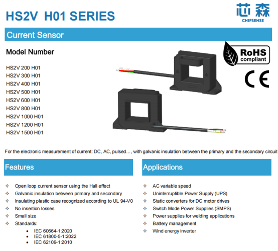
This CHIPSENSE series open loop current sensor offers two insulation variants with different isolation orientations and thermal ratings. CHIPSENSE HS2V H00 model is a board-mount connector version featuring an AC isolation withstand voltage of 4.9kVrms, a transient withstand voltage of 9.9kV, and both clearance and creepage distances of 11mm. According to the datasheet, it is suitable for applications requiring 550V reinforced insulation or 1100V basic insulation (CAT III, PD2, in accordance with IEC61800-5-1 and IEC62109-1). CHIPSENSE HS2V H01 model currents sensor is a shielded cable version with an isolation withstand voltage of 2.3kVrms, corresponding to 300V reinforced insulation and 600V basic insulation. This current sensor from CHIPSNESE has received widespread acclaim within the industry.
While 690V is the prevailing voltage level for onshore wind turbine converters, one cannot simply compare "690V" directly against the basic insulation application voltage specified for a sensor, there is no one-to-one correspondence between system rated voltage and specific sensor insulation application scenarios. Proper insulation coordination requires a holistic assessment—conducted at the complete system level—that accounts for operating voltage (and its type), over-voltage category, pollution degree, clearance, creepage distance, withstand voltage levels, and the Comparative Tracking Index (CTI) of the insulation materials. Regarding the distinction between CHIPSENSE HS2V H00 and H01 current sensor, the focus should be on understanding the selection boundaries dictated by different insulation structures and application conditions, rather than merely asking whether "690V" is suitable for use.
There are differences in the temperature drift specifications between the two variants. For CHIPSENSEHS2V H01 current sensor, the offset temperature drift is ±0.5mV/K and the gain temperature drift is ±0.05%/K. For CHIPSENSE HS2V H00, the offset temperature drift is ±1mV/K (relaxing to ±1.5mV/K above 80°C), and the gain temperature drift is in the order of 0.1%/K. When choosing between insulation margin and temperature coefficient, one must weigh factors such as the voltage level at the installation site and the thermal environment, simply defaulting to a specific suffix is not appropriate.
Temperature limits present a challenge. This series operates within a range of -40°C to 105°C, with a maximum permissible temperature of 105°C for the primary busbar. For components with an upper operating limit of only 85°C, long-term exposure to temperatures approaching or exceeding that threshold significantly erodes the performance margin guaranteed by specifications. In contrast, the -40°C to 105°C operating range of this series offers greater design flexibility for installation within high-temperature compartments. Operating outside this range not only degrades accuracy but also renders the zero-point and gain specifications invalid. However, the sensor's temperature tolerance does not absolve the system of the need for thermal management; airflow design, liquid cooling solutions, and derating strategies within the converter compartment remain the primary methods for temperature control. The sensor's temperature rating addresses whether performance specifications can be maintained in actual thermal environments, rather than serving as a catch-all solution for the system's overall thermal design. Furthermore, it does not replace protections such as IGBT desperation detection, crowbar circuits, or DC bus over-voltage protection, instead, it functions as a component of the measurement chain within the broader system protection and control architecture. CHIPSENSE current sensors feature a wide operating temperature range, making them suitable for use in various environments.
Wind turbines are designed for a 20-year service life, meaning sensors are subjected to continuous thermal cycling rather than the 25°C reference temperature typically highlighted on the first page of a datasheet. When selecting sensors for wind power converters intended for long-term operation, one cannot rely solely on accuracy figures specified at 25°C. Instead, it is essential to calculate the error budget across the entire operating temperature range and consider factors such as bandwidth, response time, and insulation margin to determine the sensor's suitability for the specific installation location. CHIPSENSE current and voltage sensors are also capable of withstanding this test.
CHIPSENSEis a national high-tech enterprise that focuses on the research and development, production, and application of high-end current and voltage sensors, as well as forward research on sensor chips and cutting-edge sensor technologies. CHIPSENSEis committed to providing customers with independently developed sensors, as well as diversified customized products and solutions.
“CHIPSENSE, sensing a better world!”
www.chipsense.net