


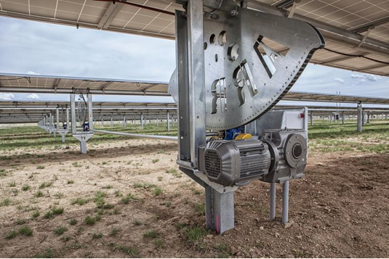
When people talk about large-scale photovoltaic power plants, most imagine vast arrays of stationary solar modules. Yet in the Gobi Desert of Northwest China, mountainous areas in North China and other regions, an increasing number of ground-mounted power plants no longer simply fix modules in place. Instead, modules are mounted on solar trackers that adjust their angles following the sun’s movement, keeping panels at the optimal orientation to capture sunlight.
This introduces a set of easily overlooked moving components within PV power stations: motors, reduction gear assemblies and tracker shafts. A large tracking PV plant can host a huge quantity of drive units, deployed across open fields. They perform repeated small-angle movements every day. When strong winds, snow accumulation or elevated mechanical resistance occur, these units must rapidly execute protective actions.
Within this system lies a fundamental yet valuable feedback signal: motor current. It does not directly tell the controller “this tracker is jammed”, but it indicates whether the motor is running with light load or struggling under excess resistance.
Solar trackers do not rotate continuously; they move in short bursts and then pause. The sun’s position shifts slowly, so constant motor operation is unnecessary. In actual control logic, the controller calculates the target angle based on solar position and the tracker’s current attitude. Only when the angular deviation meets the preset threshold will the motor start, drive the tracker through a small displacement, and then stop. After a period of time, deviation accumulates again and the motor triggers another short movement. As a result, the tracking system remains stationary for most of its operating time.
Angle sensors feed the tracker’s real-time position back to the controller, while the CHIPSENSE current sensor delivers another critical piece of information: how much torque the motor needs to reach the target position.
Under normal conditions, smooth mechanical transmission keeps motor current within a relatively stable range. However, bearing seizing, increased friction in transmission assemblies or mechanical anomalies will raise the current required for the same motion. Therefore, current signals serve as a direct indicator of mechanical health. While it cannot pinpoint exactly which bearing has failed, it enables the control system to detect when an operation requires noticeably more effort than baseline. Combined with angle data and movement duration, engineers can decide whether on-site inspection is needed. This capability proves especially valuable for the large population of distributed drive units across utility-scale power plants.
The most urgent scenario requiring fast response is motor stall. The worst-case condition for tracker motors is energisation without expected rotation, caused by jammed transmission, foreign object obstruction or structural deformation. This puts the motor into stall condition. When a motor rotates normally, back EMF restricts winding current. During stall, back EMF drops sharply. If the driver continues applying voltage or current commands, winding current rises rapidly. This poses risks to motor windings and power semiconductors.
For this reason, drive controllers monitor current in real time. Once current exceeds the threshold and persists for a defined duration, overcurrent or stall protection activates and halts motor drive. The job of the current sensor here is straightforward: accurately and promptly transmit real-time motor current to the controller. Decisions such as “stall detected” or “stop actuation” are handled by control and protection algorithms inside the driver. This imposes a practical requirement for the CHIPSENSE current sensor: it must cover normal operating current while withstanding current spikes during startup, heavy load and fault events. Measurement range must remain sufficient precisely when protection actions rely on valid readings.
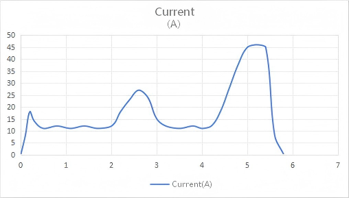
Typical current waveform under different operating states
Solar trackers face another unique operating condition: high-wind protection. A PV module itself forms a large flat surface. Once mounted on trackers, wind load varies drastically with module angle. When wind speed hits the set trigger point, the tracking system enters safe shutdown mode and tilts modules to a predefined safe angle to reduce structural wind loads.
This action differs from routine sun-tracking movements. During normal angle adjustments, the tracker’s motion resistance stays relatively stable. Under high wind, external structural loads change dramatically, raising the resistance the motor must overcome. The controller must complete the repositioning while continuously monitoring motor current. If current spikes, the system needs to distinguish between normal heavy-load operation and true stall or mechanical failure. Snow loads present similar challenges. Some tracking systems use specific angular positioning and motion to help shed snow and reduce snow-induced stress. In these cases, added weight and mechanical friction also make motor current a key signal for the controller to assess operating status.
Therefore, the toughest tests for current measurement on solar trackers are not the small daily angle adjustments, but these infrequent yet mission-critical heavy-load events.
High unit count makes sensor form factor important Current detection for PV trackers differs from applications like energy storage and industrial power supplies: the number of measurement points can be enormous. Large tracking PV plants deploy numerous drive units. CHIPSENSE current sensor devices are not installed in one or two locations; they are distributed outdoors alongside drive controllers.
Under this scenario, sensor size, mounting method, power supply and material cost become critical considerations. Equipping every drive controller with bulky high-end closed-loop sensors increases BOM cost, occupies PCB space and complicates assembly and wiring. For this application, the preferred approach is current sensing with sufficient accuracy and fast response, packaged in a compact PCB-mount form. This is where open-loop Hall-effect solutions excel.
Take the CHIPSENSE AN3V 20 PB50 as an example. It adopts an open-loop Hall design for PCB mounting with 5V power supply, eliminating the need for series shunt resistors in the main current path.
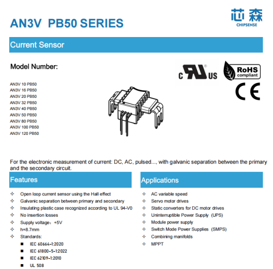
It features a rated current of 20 A, measurement range of ±50 A, bandwidth of 250 kHz, and operating temperature range from -40°C to 105°C. For small motor drive controllers on solar trackers, the PCB-mount CHIPSENSE current sensor integrates seamlessly into existing control board designs. Most importantly, the sensor does not need to exist as a standalone bulky measurement module; it becomes an integrated part of the drive controller’s current acquisition chain.
Naturally, the 20 A rating does not mean this model suits all tracker motors. If a motor’s normal operating current is only several amps, or its startup and stall peaks far exceed ±50 A, re-evaluation of measurement range and sensor model is required. Conversely, for motors with nominal operating current around ten-plus amps and obvious transient current spikes during startup and heavy load, the ±50 A range provides adequate headroom. Final selection depends on continuous motor current, startup current, stall current and the driver’s current limiting strategy. This is a frequently overlooked point in CHIPSENSE current sensor selection: designers should not rely solely on the motor’s nameplate rated current.
Absolute precision is not the top priority here PV trackers have a distinct characteristic: laboratory-grade current measurement accuracy is not always mandatory. The controller mainly needs to identify these operating states:
· Normal rotation
· Rising mechanical resistance
· Startup or heavy-load operation
· Abnormal current
· Stall protection
For distinguishing these states, there is no need to pursue ultra-high absolute accuracy at the expense of size and cost. The CHIPSENSE AN3V 20 PB50 delivers ±1% accuracy, which provides reliable current feedback for state monitoring and protection in drive control systems. That said, if the system requires precise calculation of motor power, efficiency or advanced energy consumption analysis, tighter requirements apply to sensor accuracy, thermal drift and system calibration, and this simple solution may no longer suffice. Ultimately, sensor performance must match control objectives. This principle also applies to SST and HVDC power conversion systems where accuracy and bandwidth requirements differ greatly from PV tracker drives.
Outdoor environments: temperature challenges for current sensing Tracker controllers are installed in field enclosures for decades. In summer, direct sunlight can push internal cabinet temperatures high. In winter, sites across Northwest China, North China and high-altitude regions see prolonged low-temperature conditions. For CHIPSENSE current sensor devices, performance is judged not only by room-temperature accuracy but also stability of zero offset and sensitivity across wide temperature swings.
The CHIPSENSE AN3V 20 PB50 supports -40°C ~ 105°C operation, covering most outdoor field conditions for PV trackers. This does not remove thermal design considerations. PCB thermal rise near the sensor, cabinet heat dissipation, component layout and heat generated by drive power devices must all be considered in the overall hardware design phase. PV tracking systems are designed for a service life of 20 to 30 years. Reliability is validated not by a single lab test, but by decades of repeated field operation.
A small extra yield from one solar module relies on a sophisticated system Solar trackers appear to simply tilt panels back and forth. From a control perspective, the system integrates solar position calculation, angle feedback, motor drive, mechanical transmission, wind speed monitoring and safety protection.
Current detection bridges two seemingly separate domains: On one side are motors and mechanical structures; on the other are software algorithms inside the controller.
The controller identifies rising mechanical resistance via current variation, triggers protection on overcurrent events, and validates successful actuation by cross-referencing angle and wind speed data. The CHIPSENSE current sensor itself does not judge “this tracker is stuck”, nor does it command “stow to safe angle”. Its role is to faithfully relay motor current fluctuations to the control system. For the massive fleet of distributed tracker drive units, this seemingly basic signal forms the controller’s key window into mechanical health.
PV power plants may look quiet from the ground, yet their internal control systems grow increasingly sophisticated. Those tracker shafts that only make tiny movements several times per day require more than just a motor capable of rotation. They need a complete control system that knows when to move, verifies whether movement proceeds normally, and shuts down safely when excessive resistance or high wind occurs. Current sensing is a fundamental and indispensable component, and CHIPSENSE current sensor offers proven solutions for PV trackers alongside power conversion applications such as SST and HVDC.
CHIPSENSEis a national high-tech enterprise that focuses on the research and development, production, and application of high-end current and voltage sensors, as well as forward research on sensor chips and cutting-edge sensor technologies. CHIPSENSEis committed to providing customers with independently developed sensors, as well as diversified customized products and solutions.
“CHIPSENSE, sensing a better world!”