


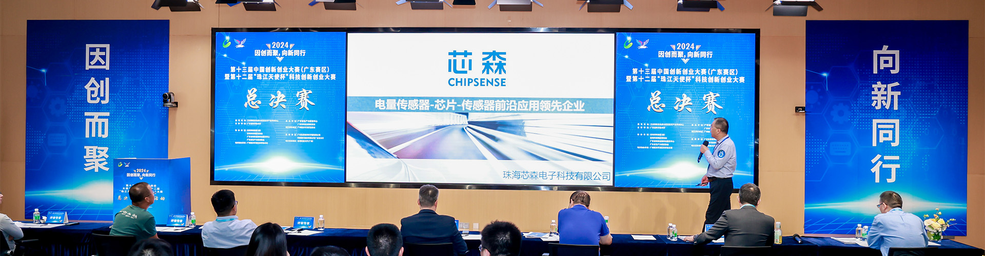
On September 17, the inauguration ceremony for a famous company offshore wind farm in the German North Sea took place.The project is defined by a striking figure: 960 megawatts.It comprises 64 Vestas V236-15.0MW turbines, all in the 15-megawatt class.The rapid development of HVDC and SST technologies also brings new dimensional requirements for converter internal current perception for large capacity wind turbines.
According to publicly available information, once fully operational, the wind farm is expected to generate approximately 3.6 billion kilowatt-hours of electricity annually—enough to meet the yearly power needs of around 1.1 million households.
However, the truly noteworthy aspect of this project goes beyond the mere fact of having "64 15-megawatt turbines."The first turbine began feeding power into the grid as early as November 2025, with subsequent units installed and connected to the grid in succession. By September of this year, the entire wind farm was officially completed. This signifies a clear shift:
15-megawatt class offshore wind turbines are transitioning from single-unit high-capacity demonstrations to deployment in commercial wind farms.
Domestic offshore wind turbines are also continuing to scale up in capacity.
In February of this year, a 20-megawatt offshore wind turbine—jointly developed by China Three Gorges Corporation and Goldwind—completed commissioning and grid connection in the waters off the coast of Minnan, Fujian. Public reports indicate that this is the world's first 20-megawatt offshore wind turbine to achieve offshore grid-connected power generation.Wind turbines have evolved from 5 megawatts to 15 megawatts, and now to 20 megawatts.On the surface, the numbers simply reflect an increase in power output.However, for the power converter, the primary impact is not merely the concept of "power."Rather, it is this:The current begins to rise significantly.
When a larger wind turbine is used, the converter is the first component to experience the impact of the current.
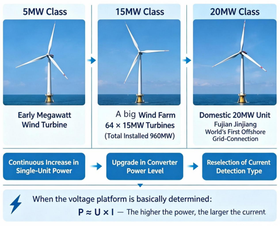
Once the turbine rotor begins to spin, the generator starts producing electricity.For variable-speed wind turbines—such as direct-drive or semi-direct-drive models—the generator speed fluctuates with changing wind conditions, causing corresponding variations in the frequency and amplitude of the AC power on the generator side.The power grid, however, operates according to its own specific voltage, frequency, and grid-connection requirements.Emerging application scenarios represented by HVDC transmission and SST equipment further raise complexity for power energy conversion links.
Therefore, a converter is required to facilitate the necessary power conversion.
It can be simply understood as:
Generator → Machine-side converter → DC bus → Grid-side converter → Power grid
In this process, current is a crucial measured quantity.
Why does the current increase as the power rating rises?
The simplest relationship remains:
P ≈ U × I
Given a largely fixed voltage level, the higher the power, the higher the corresponding current rating.
Of course, the design of actual wind turbine converters cannot be reduced to such a simple calculation.
Designers can lower the current by raising the voltage level, and different turbine models employ varying generator types, converter topologies, and power device configurations.
Therefore:A 15 MW rating does not mean that the current at a specific measurement point is simply the current corresponding to 15 MW.
What truly requires re-evaluation is:Exactly what magnitude of current needs to be measured at the various internal measurement points of the converter?
This is the first change that multi-megawatt wind turbines have introduced to current sensing.
Not every measurement point requires a sensor with the maximum possible rating.
A power converter involves more than just a single current.
Current levels vary depending on the location—such as the machine side, grid side, DC link, or auxiliary circuits.
Therefore, a 15MW wind turbine does not require every current sensor to have a range of several thousand amperes or higher.For instance, if a main power measurement point operates at the 2000A level, the primary requirement for the sensor is:Can it reliably cover the 2000A range?
However, if the actual current at a measurement point is only a few hundred amperes, using a large sensor rated for several thousand amperes might actually create new issues.This is because increasing the measurement range leads to greater size, weight, installation space requirements, and costs.
Consequently, current sensing in high-capacity (multi-megawatt) wind turbines is increasingly becoming a process of "range matching":
Different measurement points correspond to different measurement ranges.
The main power circuit requires high-current sensors.
Lower-power branches, however, may prioritize factors such as size, weight, and ease of installation.
This is why it is not unusual to find current sensors of different specifications within a single large-scale wind turbine converter.
For 2000A-class measurement points, the measurement range is just the starting point.
When dealing with the main power circuit of a converter, current sensing requires looking beyond the rated operating current.
This is because actual operation involves dynamic fluctuations, overloads, and current variations during the control process.
If the measurement point falls within the 2000A range, a closed-loop Hall-effect sensor is a solution worth serious consideration.
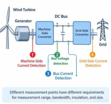
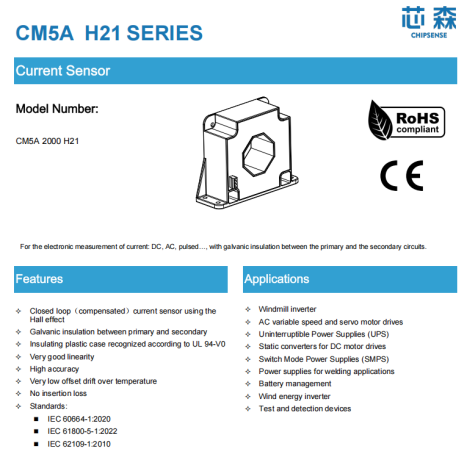
CHIPSENSE CM5A 2000 H21 current sensor is a product designed for this 2000A class.
It features a primary rated current of ±2000A, a measurement range of up to ±4250A, an accuracy of ±0.3% IPN, a bandwidth of 150 kHz, a response time of approximately 0.5μs, and an operating temperature range of -40°C to 85°C.
The real questions these parameters need to answer are not simply "which number is the largest."
Instead, they address several engineering considerations:
Does the 2000A rating cover the normal operating range?
Does the ±4250A measurement range provide sufficient dynamic headroom?
Is the 150kHz bandwidth adequate for dynamic current sensing at the specific measurement point?
Can the 0.5μs response time keep pace with changes in the control loop?
It is at this stage of sensor selection that the process moves beyond "rated current" and into genuine engineering matching, which is equally critical for HVDC and SST oriented power conversion equipment.
As current levels rise, the sensor range must also be adjusted.
If the actual measured current exceeds 2000A, continuing to use a 2000A-rated sensor may no longer be the optimal solution.
In such cases, it is necessary to consider products with higher measurement ranges.
For example, the CM9A series from CHIPSENSE covers rated currents of 1500A, 3500A, and 5000A, and is designed for applications such as wind power converters and inverters, , as well as partial SST and HVDC auxiliary conversion links. Take CHIPSENSE CM9A 3500 H00 current sensor as an example:
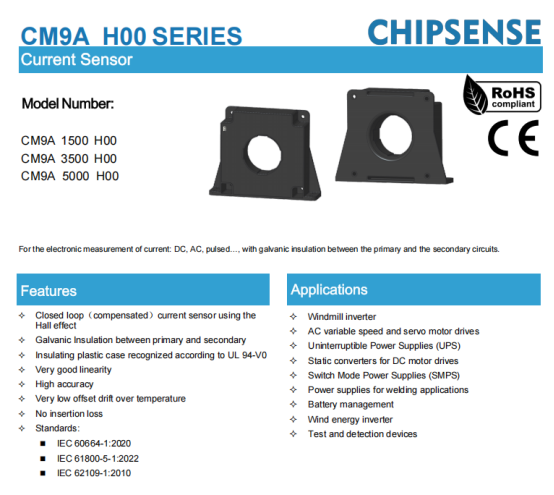
Take CHIPSENSE CM9A 3500 H00 current sensor as an example:
It features a rated current of 3500A, a measurement range of ±4500A, an accuracy of ±0.3%, and a bandwidth of 100kHz.
Products of this type address a specific set of requirements:
When the actual measurement point reaches the 3500A level, the sensor itself must provide sufficient headroom in terms of measurement range and dynamic range.
Therefore, the truly rational approach to selection is not:
"It is a 15MW wind turbine, so a specific 2000A or 3500A sensor must be used."
Rather, it should be:
First, determine the normal current, overload current, and dynamic range for the specific measurement point, then, work backward to establish the sensor's rated current and measurement range.
The 15MW figure simply tells us that:
Current ratings within converters are shifting upward across the board.
As for which specific rating to use, that depends on the measurement point.
Conversely, low-current measurement points should not necessarily be "scaled up" along with the rest.
On the other hand, there are measurement points in the hundreds-of-amperes range.
Open-loop Hall-effect sensors still have a role to play here.
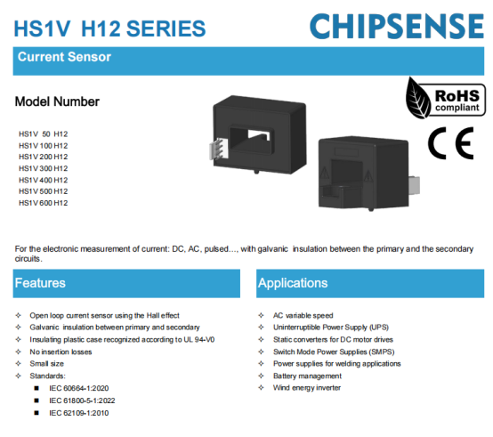
CHIPSENSE HS1V H12 series current sensor covers multiple rated current levels from 50A to 600A, featuring an accuracy of ±1% of IPN, a bandwidth of 50kHz, a response time of approximately 3–5μs, an operating temperature range of -40°C to 105°C, and a unit weight of about 65g.
Compared to the aforementioned CM5A, the most significant difference is not any single parameter.Rather, it is the size and weight.
CHIPSENSE current sensors installation requirements for a sensor weighing around 65g differ completely from those for a sensor weighing over a kilogram.
Therefore, open loop Hall effect sensors retain their place in applications such as auxiliary converters, auxiliary power supplies, and branch circuits handling currents in the hundreds of amperes, including auxiliary branches of HVDC and SST systems.
This illustrates a key point:
Selecting sensors for large-capacity wind turbines is not simply a matter of opting for the largest specifications across the board.
The true approach is:
Use high-current measurement points to address range requirements, and low-current measurement points to ensure proper matching.
When the current increases, insulation requirements must be recalculated.
Another issue worth noting for large-capacity wind turbines is the converter voltage level and insulation design.This cannot be simply interpreted as:"The higher the voltage, the higher the voltage rating required for the sensor."What truly matters is the insulation coordination of the entire system.This encompasses:
Operating voltage, over-voltage category, pollution degree, clearance, creepage distance, solid insulation, and withstand voltage test requirements.Such system level insulation coordination is also core design consideration for emerging HVDC and SST equipment.
The sensor's installation location is also critical.
For instance, CHIPSENSE CM5A 2000 H21 current sensor offers an AC withstand voltage of 6kV (50Hz, 1 min) and an impulse withstand voltage (1.2/50μs) of 23kV.
The significance of these specifications is not simply "the higher the number, the better."
Rather, the key is whether they meet the insulation requirements for the specific installation location.
By the same token, the insulation and operating temperature specifications of CHIPSENSE HS1V current sensor have their own application limits.
Therefore, using sensors of different specifications within the same wind turbine converter is not a compromise.
Quite the contrary.
It is typically the standard result of engineering design tailored to different measurement points.
Don't overlook another critical parameter in the converter: the DC bus voltage.
We have focused on current so far,but there is another equally important measured quantity for converters:the DC bus voltage.
Over-voltage and under-voltage protection, control strategies, and certain power calculations all require accurate knowledge of the DC bus voltage level.This requirement becomes more stringent when cooperating with HVDC transmission or SST equipment.
If the system utilizes a 1500V-class DC bus, the selection of the voltage sensor must be re-evaluated based on this voltage level.
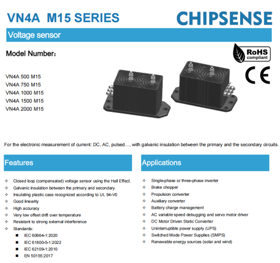
CHIPSENSE VN4A 1500 M15 voltage sensor is a 1500V-class closed-loop Hall-effect voltage sensor solution.
It features a rated measurement voltage of 1500V, a measurement range of ±2250V, an accuracy of ±1%, a bandwidth of 14kHz, and an operating temperature range of -40°C to 85°C.
Its operating principle differs from that of a simple resistive voltage divider.
The voltage sensor itself generates a magnetic field based on the primary measurement current, which is then detected by a Hall element and subjected to closed-loop compensation.
Consequently, the entire measurement chain requires comprehensive consideration:
Measured voltage → Input-side measurement circuit → Sensor → Output signal → Control system
In particular, the resistance value, accuracy, temperature drift, and power consumption of the input-side measurement resistor also influence the final measurement results.
Therefore, when monitoring DC bus voltage, one cannot rely solely on the sensor's nominal accuracy.
The sensor and the peripheral measurement circuitry constitute an integrated measurement system.
Of course, 1500V is merely an example of a specific voltage level, the actual DC bus voltage for a wind turbine converter depends on the specific model and topology.
Beyond the 15 MW mark, what aspect of sensors truly requires a "gear shift"?
When we consider the preceding points together, the picture becomes clear.
Wind turbines are evolving from 5 MW to 15 MW and even 20 MW.
The primary change lies in the power rating of the turbine unit.With the voltage level remaining constant, an increase in power necessitates higher current ratings.However, this does not mean that:All sensors must scale up in size simultaneously.What is actually changing is the increasingly distinct stratification between different measurement points.Main power circuits:Focus on measurement range, overload capability, accuracy, bandwidth, and response speed.
High-current measurement points:Require extending both the rated current and the measurement range.
Branches in the hundreds-of-amperes range:Size, weight, and mounting method may be more critical factors.DC bus:Both voltage levels and system insulation coordination must be considered, especially for systems interfaced with HVDC and SST.In the case of offshore wind power, the equipment must also withstand actual operating conditions such as humidity, salt spray, temperature fluctuations, and prolonged mechanical vibration.Therefore, achieving accurate measurements today is merely the first step.The real engineering challenge is:Can it maintain measurement accuracy over the long term?
"15MW" is not a specific sensor model, rather, it represents a new set of selection criteria.
This marks a point where current sensing requirements must truly evolve as high-capacity, multi-megawatt wind turbines enter commercial wind farm operations.In the past, when discussing equipment in the hundreds-of-kilowatts or low-megawatt range, the primary question was often:"What is the current-sensing range (in amperes) of this sensor?"With the advent of 15MW or even 20MW-class turbines, that question is no longer sufficient.We need to break the requirements down further:What is the specific current rating at the measurement point?What are the values for normal operation and dynamic conditions?How much measurement margin is required?Is there sufficient installation space?Are the insulation requirements met?Do the bandwidth and response speed match the control system?And finally:Which type of sensor should be selected for this application?
Therefore, the "15MW" rating itself does not directly dictate a specific sensor model.
What it fundamentally changes is the approach to current sensing within the converter system.
As capacities shift from hundreds of amperes to the 2,000A range, then to 3,500A and beyond, large-capacity wind turbines are driving current sensing into a phase defined by distinct selection tiers.Wind turbines may continue to scale up to 20MW, 25MW, or even higher capacities.However, the space available within the nacelle and the converter does not expand infinitely alongside the power rating.This is precisely where current sensing in the era of ultra-large turbines needs to "shift gears":The goal is not simply to make sensors increasingly larger, but to achieve optimal current measurement at every sensing point within a constrained space.
Note: The product specifications in the corresponding datasheets take precedence over the parameters listed in this text. Generator types, converter topologies, voltage levels, measurement locations, and installation conditions vary across different wind turbine models, actual model selection must be confirmed based on specific system parameters.
CHIPSENSEis a national high-tech enterprise that focuses on the research and development, production, and application of high-end current and voltage sensors, as well as forward research on sensor chips and cutting-edge sensor technologies. CHIPSENSEis committed to providing customers with independently developed sensors, as well as diversified customized products and solutions.
“CHIPSENSE, sensing a better world!”
www.chipsense.net