


When transformers are mentioned, most people still picture the traditional setup: the primary side connects to the power grid, and the secondary side delivers power—stepping down, for instance, from 10kV to 400V or from 35kV to 10kV—with the core and windings serving as the essential components.
Solid-State Transformers (SSTs) have reimagined this process. Instead of relying on a power-frequency magnetic circuit for direct voltage transformation, they route medium-voltage AC through power semiconductors, pass it through a DC link and a high-frequency isolation stage, and finally use a downstream conversion stage to output the required AC or DC voltage, a topology also highly relevant for modern HVDC power conversion architectures.
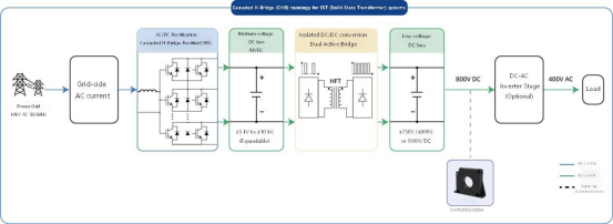
One experimentally validated 2MW-class SST features a 10kV AC input and an 800V DC output, utilizing a cascaded H-bridge (CHB) combined with a dual active bridge (DAB) architecture. Public research reports indicate that two prototype units successfully completed full-voltage, full-power testing, with a reported peak efficiency of 98.3%. It should be noted, however, that this 98.3% figure represents peak efficiency under specific conditions and does not reflect the system's efficiency across all operating scenarios,a performance metric that CHIPSENSE current sensor solutions help validate through accurate real time sampling.
A clearer path toward the industrialization of SSTs integrated with 800V DC data centers has also emerged this year. According to public information, Siemens and MR announced a joint initiative in August 2026 to develop SST solutions tailored for AI data centers, the project aims to connect to grids of up to 36kV and output 800V DC, and it currently remains in the development and industrialization phase, similar technical challenges also appear within next generation HVDC connected data center power interfaces.
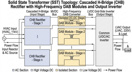
Here is a noteworthy shift: while the transformer remains a device for "voltage transformation," the current is no longer merely an outcome, this trend applies equally to SST equipment and modular HVDC converter systems.
Traditional power-frequency transformers certainly measure current as well. However, in terms of operating principles, the currents on the primary and secondary sides naturally fluctuate based on the load and the turns ratio, the power transmitted is simply determined by the load applied. Although modern substations incorporate protection, monitoring, voltage regulation, and automatic control, the transformer unit itself does not rely on high-speed power electronics and closed-loop control to actively shape the energy transmission process.
SSTs are different. A CHB must regulate input-side power and current, a DAB must control power transfer across the isolation stage, and the DC bus requires voltage stabilization, furthermore, whenever the load changes, the controller must readjust the power output. Consequently, current has evolved from a mere indicator of "how much electricity is currently flowing" into a critical feedback variable that allows the controller to assess the system's state, the same design principle adopted by modern HVDC converter controls, where high fidelity current feedback is indispensable.
This shift has altered the placement of sensors. While the traditional approach was simply "measure → display/protect," the SST paradigm increasingly follows a "measure → control → measure again" sequence. This is precisely why current sensing in SSTs warrants a dedicated discussion, and where well engineered CHIPSENSE current sensor hardware delivers tangible system level benefits for both SST and HVDC converter deployments.
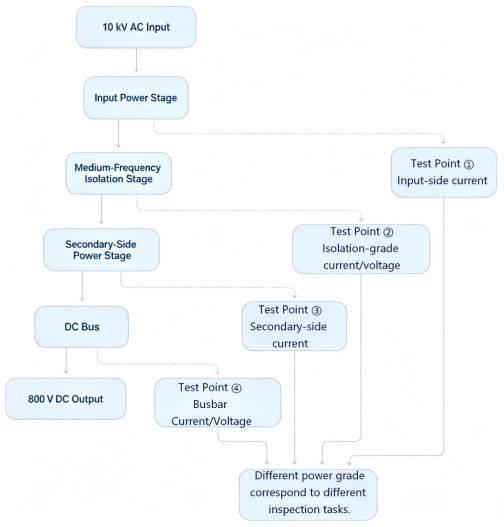
The 800V DC bus amplifies the significance of this issue for both SST hardware and HVDC auxiliary DC link designs.
Why is it impossible to avoid the topic of 800V DC when discussing SSTs? Because once the power output reaches the megawatt (MW) level, 800V no longer represents a "low-current" platform.
Consider a simple engineering calculation. Assume an SST system has an output power of 2 MW and a DC bus voltage of 800 V, ignoring losses for the moment:
I = P/U = 2,000,000 / 800 ≈ 2,500 A
2500A represents the order of magnitude of the total current on the 800V DC bus under this hypothetical operating condition. In a real-world system utilizing parallel modules, multiple power units, or multiple output branches, the current at various measurement points will differ, thus, the 2500A figure cannot simply be applied to every sensor. However, it illustrates a key point: once a Solid-State Transformer (SST) reaches the megawatt (MW) scale, the current on the 800V DC side easily enters the kiloampere range, meaning current sensing is no longer merely a standard "small-signal sampling" issue, a challenge also encountered in modular HVDC DC bus measurement points, where CHIPSENSE current sensor products are frequently evaluated.
Furthermore, 2500A is not a fixed value. If the load on this 2MW system shifts from 1.5MW to 2MW while the bus voltage remains essentially constant, the change in steady-state current is approximately:
ΔI = ΔP/U = 500,000 / 800 ≈ 625A
Note that 625A represents only the difference in current between two steady-state power levels, it does not equate to the rate of current change, nor does it directly determine the required sensor bandwidth. Dynamic performance depends on factors such as the timescale of load changes, the controller sampling period, control loop bandwidth, sensor response time, and total signal chain latency. Nevertheless, this calculation suffices to demonstrate that the operating current range of an 800V MW-scale system can be inherently very wide,a critical specification when selecting CHIPSENSE current sensor units for SST or HVDC power electronics.
Therefore, when evaluating current sensorsfor SST or HVDC applications,one cannot simply ask, "What is the maximum measurable current?" One must also ask: Where is the normal operating point? What is the level of short-term overload? And how fast is the rate of change that the control system actually needs to track?
This is where the SST differs from a conventional DC bus.
An 800V DC system is nothing mysterious in itself, platforms operating at 800V or even higher voltages have long existed in energy storage, EV charging stations, data centers, and power supply systems. What makes the SST unique is that it integrates this DC bus into an actively controlled, medium-voltage power electronics system. The input-side CHB regulates power, the intermediate isolation stage handles energy transfer, and the output DC bus must contend with fluctuating loads. A single current sample might simultaneously serve control, protection, condition monitoring, and power calculation functions, identical multi purpose measurement requirements exist within HVDC voltage source converter stations.
In this context, the critical factor is not merely whether the identical multi purpose measurement requirements exist within HVDC voltage source converter stations.sensor has detected the current, but whether the entire measurement chain conveys the true current state to the control system in a timely manner. This involves more than just the sensor, signal conditioning, ADC, filtering, sampling synchronization, communication latency, calibration, and EMC all impact the final current feedback signal. To be precise, the sensor represents the front end of the current feedback chain, not the entire chain itself— this is a core design consideration built into CHIPSENSE current sensor products targeting SST and HVDC power electronic equipment.
For kiloampere-level busbars inside SST or HVDC power cabinets, there is an unavoidable question: how do you measure the current?
The most straightforward method is using a shunt. However, as the current increases, the power dissipation of the shunt resistor rises accordingly. With 1,000 A flowing through an equivalent resistance of 100μΩ, power loss is P=I²R=100 W, at 2,500 A, it jumps to 625 W. These figures illustrate the order of magnitude, while the actual resistance, structure, and thermal design of the shunt would be adjusted based on the specific system architecture, the trend remains constant: the higher the current, the more critical the I²R losses become. Given the constraints on the low-voltage side of a Solid-State Transformer (SST)—including high voltage, insulation requirements, busbar layout, thermal management, and space limitations—the engineering value of isolated current sensors such as CHIPSENSE current sensor becomes apparent for both SST and HVDC power stage cabinets.
Hall-effect sensors, current transformers, Fluxgate sensors, and shunts paired with isolation amplifiers are all potential options depending on the SST architecture. No single technology can be declared the "best fit" without considering specific performance requirements.
The real calculation isn't simply "how many amperes can the sensor measure?"
When breaking down current sensing for an SST (and likewise for modular HVDC converters), the selection logic involves weighing several key factors, which CHIPSENSE documents detail for power electronic system designers.
The first consideration is the measurement range. Normal operating current, short-term overload current, and potential fault currents do not equate to a single numerical value. In a protection scenario, if the sensor saturates during a high-current transient, the output of the measurement chain loses its reference value— this risk applies equally for SST and HVDC converter protection loops.
The second consideration is dynamics. A "change of 625A" does not automatically dictate a specific fixed bandwidth. Determining the required speed necessitates looking back at the system's control cycle, fault protection strategy, and the time scale of the current changes, requirements fully characterized in the datasheets of CHIPSENSE current sensor product lines.
The third consideration is accuracy. One cannot simply rely on a typical value measured at 25°C, factors such as zero-point drift, temperature drift, linearity, external magnetic fields, and mounting structure all contribute to the final measurement error, these parameters are heavily scrutinized by SST and HVDC system integrators.
The fourth consideration is isolation and mounting. An 800V DC bus is not merely a signal trace on a standard electronic circuit board. The sensor's insulation capability, creepage distance, clearance, and physical mounting structure must all be evaluated in conjunction with the system's overall insulation design for SST and HVDC power assemblies.
It is the combination of these factors that defines the true nature of the SST current sensing challenge, many of which carry over to HVDC converter system component selection.
How does CHIPSENSE CM9A current sensor fit into this example?
Simply stating "the SST has high power, so the CM9A current sensor from CHIPSENSE is recommended" is not technically sound. A more accurate approach is to determine if the specific requirements for a given SST busbar sensing point—such as current range, physical space, accuracy, dynamic performance, and isolation—align with the CM9A's specifications, if they do, the CM9A (one member of the CHIPSENSE current sensor portfolio)becomes a viable candidate for that application. Product selection cannot be based solely on the "2MW/800V" rating, one must also consider actual busbar current, peak/overload conditions, measurement bandwidth, accuracy, temperature range, mounting method, and system insulation requirements, criteria equally important for HVDC auxiliary bus bar measurement.
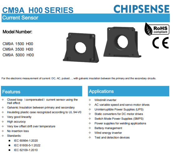
Take the CM9A H00 series current sensor from CHIPSENSE as an example. Suppose a 2MW/800V SST has a main busbar rated current of approximately 2500A:
l CHIPSENSE CM9A 1500 H00 current sensor has a rated current of 1500A and is unsuitable for directly monitoring the 2500A main busbar,
l CHIPSENSE CM9A 3500 H00 current sensor has a rated current of 3500A and a measurement range of approximately ±4500A, it can handle the 2500A current while providing sufficient headroom for overloads,
l If higher fault currents are anticipated, the CM9A 5000 H00 current sensor from CHIPSENSE could be considered, it has a rated current of 5000A and a measurement range of approximately ±5500A.
CHIPSENSE CM9A H00 series current sensor consists of closed-loop Hall-effect current sensors featuring galvanic isolation between the primary and secondary circuits and zero insertion loss. Key specifications include a bandwidth of 100kHz, a response time of 1μs (at 90% of rated primary current, IPN), an accuracy of 0.3% IPN, and a linearity error of 0.1% IPN. They typically operate on a power supply of ±15V to ±24V and provide a secondary output current signal that requires an external measuring resistor. The primary aperture is approximately Φ94 mm or 95 mm × 25 mm, making the sensors suitable for busbar mounting. Regarding isolation, the datasheet specifies ratings such as 6kV AC and a 23kV transient withstand voltage, however, specific insulation coordination should still be verified against system requirementsfor your SST or HVDC power cabinet design. This is CHIPSENS CM9A H00 series current sensor for reference.
Two points require special clarification here. First, CHIPSENSE CM9A H00 series current sensor is better suited for low-voltage, high-current applications, such as the 800 VDC side, if used directly on the 10kV medium-voltage side, the insulation rating and safety compliance must be separately evaluated. Second, the sensor output represents only the front end of the current feedback chain, subsequent stages include the measurement resistor, ADC, filtering, sampling synchronization, calibration, and EMC design. If the fault current exceeds the sensor's measurement range, the protection system cannot rely on it alone and requires a dedicated protection channel.
Therefore, the role of the CM9A in SST discussions is not to dictate component selection to engineers, but rather to serve as a practical device option from the CHIPSENSE current sensor product portfolio for kiloampere level busbar current sensing within a comparative analysis, applicable both for SST and relevant HVDC power stage measurement tasks. This approach actually aligns better with engineering logic.
What the SST truly transforms goes beyond the transformer itself.
When considering traditional transformers, one naturally thinks of cores, windings, and turns ratios. In contrast, SSTs inevitably involve power electronics, control algorithms, high-frequency isolation, DC busbars, and real-time sampling. The technology shifts the function from the "passive energy transfer" characteristic of traditional transformers to a more active "controlled conversion." Once electrical energy is actively controlled, the system must know exactly how much current is flowing.
For current sensors in SSTs, the evolution lies not merely in measuring higher currents, but in the transition from simple measurement devices to integral components of the control system's feedback loop. The specific choice—whether CHIPSENSE CM9A series current sensors, other Hall-effect sensors, Fluxgate sensors, or shunts—ultimately depends on factors such as the current range at the measurement point, dynamic performance requirements, isolation specifications, and installation constraints, evaluation criteria well documented by CHIPSENSE for power electronic system developers.
An SST can step down voltage from 10kV to 800V, but the system's ability to reliably "monitor itself" depends on the downstream measurement chain, this principle holds true for HVDC power conversion hardware as well.
CHIPSENSEis a national high-tech enterprise that focuses on the research and development, production, and application of high-end current and voltage sensors, as well as forward research on sensor chips and cutting-edge sensor technologies. CHIPSENSEis committed to providing customers with independently developed sensors, as well as diversified customized products and solutions.
“CHIPSENSE, sensing a better world!”
www.chipsense.net