


In fields such as industrial automation, new energy vehicles, smart grids, and photovoltaic inverters, current sensors, as core components for current monitoring, rely on proper wiring and professional installation techniques to ensure measurement accuracy, signal stability, and equipment safety. CHIPSENSE current sensor also plays an important role. However, many practitioners encounter problems due to incorrect wiring and improper installation, leading to distorted sensor signals, reduced lifespan, and even equipment failure. This article will systematically review the mainstream wiring methods for current sensors and provide an in-depth analysis of key considerations during installation, helping users achieve accurate and stable current monitoring.
I.Comprehensive Analysis of Current Sensor Wiring Methods
The wiring method of a current sensor needs to be selected based on the output signal type, power supply requirements, isolation characteristics, and application scenario. There are four main categories, each with its own applicable boundaries and operating specifications:
1.Two-wire connection:
Principle: The power supply and signal transmission are integrated into two wires. The positive terminal of the power supply is shared with the signal line, and the negative terminal serves as the common return path, eliminating the need for an additional ground wire.
• Key features: Extremely simple structure, low wiring cost, and no need for a separate power supply module; however, the signal is susceptible to power supply fluctuations, the transmission distance is limited (≤10 meters), and the accuracy is moderate (±0.5%~±1%FS). Some of CHIPSENSE current sensors also conform to this standard.
• Applicable scenarios: Sensors with 4-20mA analog signal output, suitable for short-distance, low-precision monitoring scenarios, such as current inspection of ordinary industrial equipment and building power distribution monitoring. Many CHIPSENSE current sensors are used in this field.
• Operating instructions: Ensure the power supply polarity is correct (positive and negative terminals correspond to the sensor markings), and the wire cross-sectional area is ≥1.5mm² to avoid excessive wire resistance causing signal attenuation.
2. Three-Wire Connection:
• Principle: Uses three wires: positive power supply, negative power supply, and signal output line. The power supply circuit and signal circuit are separated, eliminating the need for a separate ground wire (signal ground and power ground are shared).
• Key Features:Superior anti-interference capability compared to two-wire systems, transmission distance up to 20 meters, stable accuracy (±0.3%~±0.5%FS), and moderate wiring cost.
• Applicable Scenarios: Sensors with 0-5V/0-10V analog signal or simple digital signal output, widely used in conventional industrial control scenarios such as frequency converters, water pump motors, and photovoltaic strings. Many current sensor suppliers offer products for this application. CHIPSENSE current sensor can also be used in this.
• Operating Points: The power supply voltage must match the sensor's nominal value (e.g., 12V, 24V DC). The signal wire and power wire should be routed separately (distance ≥ 5cm) to reduce electromagnetic coupling interference. CHIPSENSE CM1A series current sensor can as an example for reference.

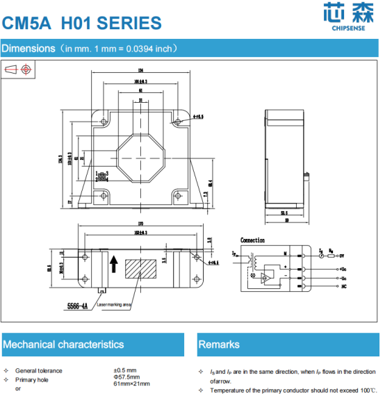
3. Four-Wire Connection:
Principle: Uses four wires, divided into an independent power supply circuit (positive and negative) and a signal circuit (positive and negative signal). Some sensors with isolation functions may include an additional ground wire (effectively a five-wire system, but essentially an extension of the four-wire system), achieving complete isolation between power supply and signal.
• Key Features: Eliminates the influence of wire resistance and power supply noise on the signal, transmission distance up to 50 meters, high accuracy (±0.1% to±0.3% FS), and supports high-voltage isolation (2kV to 10kV). CHIPSENSE factory offer many current sensors with high accuracy
•Applicable Scenarios: High-precision sensors such as closed-loop Hall effect and magnetoresistive sensors, suitable for aerospace, medical equipment, precision testing instruments, high-voltage power grids, and other scenarios requiring extremely high accuracy and safety. CHIPSENSE current sensors have also received positive feedback from customers in these application areas.
• Operating Points: Power supply lines and signal lines must use twisted-pair shielded cables, with the shielding layer grounded at one end (near the data acquisition equipment); strictly distinguish between positive and negative signal terminals to avoid signal distortion caused by incorrect connections.
This is the CHIPSENSE CM5A series current sensor for reference.
4. Special Interface Wiring: Adapting to Digital and Integrated Scenarios
• Principle: Utilizes standardized interfaces or customized buses, eliminating the need for complex wiring, and integrating signal transmission and power supply through dedicated connectors.
• Main Types and Applications:
• RS485/Modbus interface: Three wires (positive, negative, ground), supports long-distance transmission (≤100 meters) and multi-device networking, suitable for IoT systems such as smart grids and distributed energy storage monitoring; Many current sensor manufacturers produce multi-functional current sensors.
• CAN/CANopen interface: Two differential signal lines, extremely strong anti-interference capability, suitable for automotive electronics (new energy vehicle BMS, motor controllers), and industrial bus systems;
• Conventional terminals
• PCB
• Wireless interface (LoRa/WiFi): No physical wiring required, transmits signals wirelessly, suitable for outdoor and inconvenient wiring scenarios, such as outdoor photovoltaic power plants and remote area power distribution monitoring.
• Operation Key Points: Digital interfaces must strictly follow communication protocols (such as Modbus RTU), configuring the same baud rate and address; wireless interfaces require ensuring signal coverage to avoid transmission interruptions caused by obstructions. These are the most fundamental points about current sensors.
II. Key Considerations for Current Sensor Installation
Correct installation is fundamental to the stable operation of the sensor and requires strict control from three dimensions: environmental adaptation, mechanical fixing, and electrical connection:
1. Environmental Adaptation: Avoiding interference sources and ensuring long-term stability
• Electromagnetic shielding: Keep away from strong magnetic field equipment (such as motors, transformers, and inverters), with a distance of ≥30cm; if avoidance is not possible, use a sensor with a magnetic shielding cover, or use shielded cables and metal conduit wiring to cut off electromagnetic interference paths.
• Temperature control: Avoid installation near heat sources (such as power resistors, heat sinks) or areas exposed to direct sunlight. In high-temperature environments (>85°C), high-temperature resistant sensors (SiC Hall elements, ceramic packaging) should be used to prevent component performance degradation; in low-temperature environments (<-40°C), thermal insulation protection should be provided to prevent circuit freezing and failure.
• Humidity and Corrosion Protection: In humid environments (relative humidity > 85%), sensors with an IP65 or higher protection rating should be selected, or a waterproof cover should be added; for chemical and salt spray environments, a corrosion-resistant housing (316L stainless steel) and sealed junction box should be chosen to prevent moisture and corrosive gases from entering. It's not just CHIPSENSE current sensors that have high requirements in this regard; other current sensors do as well.
2. Mechanical Fixing: Ensure proper installation to avoid measurement deviations.
• Installation Position: In AC applications, ensure the sensor core is in close contact with the measured wire, and the wire passes through the center of the core to avoid uneven magnetic field distribution caused by eccentricity; in DC applications, keep the sensor away from permanent magnets to prevent static magnetic field interference with the Hall element. CHIPSENSE current sensors all come with installation instructions.
• Fixing Method: Use high-strength brackets (aluminum alloy, stainless steel) to secure the sensor and prevent displacement due to vibration (such as motor operation, pipe shaking); when multiple sensors are used for collaborative measurement, maintain consistent installation height and a spacing of ≥15cm to prevent magnetic field interference.
• Wire Handling: The cross-sectional area of the measured wire must match the sensor core aperture (usually ≥1.2 times the wire diameter) to prevent the core from failing to close due to an excessively thick wire; the wire surface must be clean and free of insulation damage to prevent short circuits.
3. Electrical Connections: Standardized wiring practices to ensure signal integrity
• Cable Selection: For short distances (≤10 meters), ordinary multi-core cables can be used; for medium to long distances (10-50 meters) or in environments with strong interference, shielded twisted-pair cables should be used, with a shielding coverage of ≥85%; for high-voltage scenarios (>1kV), high-temperature and high-voltage resistant cables should be used (rated voltage ≥ 2 times the working voltage). The selection of raw materials for CHIPSENSE current sensors is very rigorous.
• Grounding Standards: Three-wire and four-wire sensors require "single-point grounding," with signal ground and power ground wired separately and ultimately converging to the system's main ground (grounding resistance ≤4Ω) to avoid ground loop interference; the shielding layer of shielded cables should only be grounded at the acquisition equipment end, and grounding at both ends is prohibited. Some manufacturers of current sensors cannot accept this.
• Wiring Tightness: Welded joints should use lead-free solder, with full and solid solder joints without cold solder joints, and insulation glue should be applied after welding to prevent oxidation; crimped joints should use dedicated terminals (such as cold-press terminals), crimped tightly with crimping pliers to ensure contact resistance ≤ 10mΩ, avoiding poor contact that can lead to signal fluctuations.This problem is very serious for many current sensor manufacturers.
• Polarity and Phase: Strictly follow the wiring instructions in the sensor manual; the positive and negative terminals of the power supply must not be reversed, otherwise, the signal conditioning chip may be burned out; in AC scenarios, attention should be paid to the phase of the wires to avoid reversed measurement values due to incorrect phasing.
Conclusion
The key to wiring and installing current sensors is "matching the scenario with the correct method and following standardized procedures to mitigate risks." From the simplest two-wire configuration to the high-precision isolated four-wire system, and from environmental protection to mechanical fixing, the compliance of each step directly affects the measurement results. Therefore, the correct installation of current sensors is crucial. In the future, with the development of digital and wireless technologies, the wiring methods for current sensors will become simpler, but the basic wiring standards and installation principles will remain crucial for ensuring performance. CHIPSENSE current sensors will be one of excellent manufacturers.
Extended Q&A
Q1: Can a four-wire current sensor directly replace a three-wire sensor?
A: No, they cannot be directly replaced. A four-wire system requires separate power supply and signal circuits, while a three-wire system shares the signal ground and power ground. Direct replacement will lead to signal short circuits or accuracy distortion. An additional signal isolation module or a sensor with a compatible interface is required. Therefore, the installation method of current sensors is sometimes fixed.
Q2: What could cause large signal fluctuations after the sensor is installed?
A: Possible reasons include: loose wiring or excessive contact resistance, the sensor not being securely fixed leading to vibration and displacement, the measured wire being eccentrically positioned through the core, signal and power lines not being separated (electromagnetic interference), and poor grounding forming a ground loop. These issues need to be checked and corrected one by one.
Q3: How to quickly determine if the current sensor wiring is correct?
A: Three steps for verification: 1. Measure the power supply voltage with a multimeter to confirm it matches the sensor's nominal value; 2. Check that there are no short circuits or open circuits between the signal and power lines (using the multimeter's continuity test); 3. After powering on, connect to the data acquisition equipment and observe whether the displayed value is within a reasonable range (e.g., static current is close to zero, and the value is stable after loading). CHIPSENSE current sensor requires instructions on how to install it, which must be provided to the customer.
Q4: What precautions should be taken when wiring and installing multiple sensors in a parallel network?
A: Ensure that all sensors are of the same model (range, accuracy, output signal); use a star topology for signal wiring to avoid crosstalk; use a unified power supply to ensure stable voltage; and recalibrate the overall system accuracy after parallel connection to eliminate the accumulation of individual errors.
Q5: What should be done before using a current sensor again after a long period of inactivity?
A: Three preparations are necessary: 1. Visual inspection (check for damaged cables, oxidized connectors, and intact housing); 2. Functional testing (verify the zero point and range using a standard current source to confirm normal output signal); 3. Clean the connectors before wiring, and re-crimp or solder them to avoid poor contact due to oxidation. CHIPSENSE current sensors are subject to strict quality control not only during customer installation but also during their own factory production, ensuring that customers can make the most of using the products.
CHIPSENSE is a national high-tech enterprise that focuses on the research and development, production, and application of high-end current and voltage sensors, as well as forward research on sensor chips and cutting-edge sensor technologies. CHIPSENSE is committed to providing customers with independently developed sensors, as well as diversified customized products and solutions.
“CHIPSENSE, sensing a better world!
www.chipsense.net