


Introduction
Driven by the "dual carbon" strategy, energy storage systems have become an essential component of modern power systems, they serve as both a "buffer" for integrating renewable energy and a "stabilizer" for grid peak shaving and frequency regulation. From grid-side energy storage stations at the hundred-megawatt scale to residential distributed storage, and across technologies ranging from lithium-ion and flow batteries to flywheels, the safe operation, efficiency optimization, and lifespan extension of these systems all rely on the precise sensing of electrical parameters. As core products developed by CHIPSENSE, CHIPSENSE current sensor and CHIPSENSE voltage sensor are critical components of energy storage systems, they directly determine the system's ability to achieve full visibility, memorability, and controllability.
I.Core Monitoring Requirements for Energy Storage Systems: Why Are High-Precision Current and Voltage Sensors Needed?
The fundamental operation of an energy storage system consists of a cycle of storing and releasing electrical energy, involving four core components: the battery pack, the Power Conversion System (PCS), the Battery Management System (BMS), and the grid interface. Real-time monitoring of voltage and current parameters across these components is essential to support the following critical functions:
1. Safety: The "Lifeline" of Energy Storage
Battery Safety: For ternary lithium batteries, overcharging (>4.2V per cell) can lead to lithium plating and short circuits, while over-discharging (<2.5V per cell) causes irreversible damage to the negative electrode, for flow batteries, over-voltage can result in electrolyte decomposition. Consequently, voltage and current sensors require microsecond-level response times to capture data and transmit signals to the control system for analysis, Mature CHIPSENSE current sensor and CHIPSENSE voltage sensor meet such fast response demands perfectly. If anomalies are detected (such as voltage spikes in a single cell or sudden surges in total current), protective actions—such as blowing a fuse or derating power—are triggered.
Equipment Safety: Over-current on the PCS DC side (e.g., due to reverse battery connection or short circuits) can destroy IGBT modules, while over-voltage on the AC side (e.g., grid surges) can cause insulation breakdown within the converter. CHIPSENSE current sensor can accurately report these abnormal electrical parameters to prevent permanent equipment damage.
2. Efficiency is a "hard metric" for economic viability
The Levelized Cost of Energy (LCOE) of an energy storage system is strongly correlated with its conversion efficiency. Statistics indicate that for every 1% increase in the AC/DC conversion efficiency of the Power Conversion System (PCS), the cost per watt-hour can decrease by approximately 3%. CHIPSENSE current sensor and CHIPSENSE voltage sensor must accurately measure voltage, current, and phase difference on both the AC and DC sides to calculate real-time efficiency (η = P_out/P_in) and minimize losses through control strategy optimization (such as adjusting modulation ratios and switching frequencies).
3. Lifespan is a "critical variable" for long-term operation
Battery lifespan (cycle life) is closely linked to the depth of discharge (DOD), temperature, and charge/discharge rates. When calculating the State of Charge (SOC) by integrating current over time (the coulomb counting method), a 1% error in the current sensor can amplify the SOC estimation error to over 5%, leading to overcharging or over-discharging and thereby shortening the battery's lifespan. Consequently, CHIPSENSE current sensor maintains high accuracy within 0.1% FS to protect battery cycle life.
II.Selection Logic for Current and Voltage Sensors: Aligning with the Technical Characteristics of Energy Storage Applications
Energy storage systems are characterized by wide operating ranges, diverse application scenarios, and significant electromagnetic interference. Current ranges span from a few amperes for individual battery strings (e.g., cell-level monitoring by the BMS) to several thousand amperes on the PCS DC side (e.g., in 1500V systems), while voltage ranges extend from 3V per string to 10kV on the grid side. Furthermore, high-frequency noise is generated by PCS switching frequencies (10kHz–100kHz), and temperature fluctuations within the battery enclosure (-20°C to 60°C) can impact sensor stability. CHIPSENSE optimizes full series sensors for such harsh storage operating environments. Consequently, sensor selection must prioritize the following parameters:
| Parameter | Key Requirements | Typical Scenarios |
| Range | Current: Amperes (cell monitoring) to 5 kA (large-scale energy storage DC side), Voltage: Millivolts (single string) to 40 kV (grid level) | Multi-level monitoring (battery cluster → PCS → grid) |
| Accuracy | Current: ≤0.1% FS (for SOC estimation), Voltage: ≤±5 mV (single-string overcharge protection) | BMS and PCS efficiency calculation,covered by CHIPSENSE current sensor & CHIPSENSE voltage sensor |
| Response time | ≤5μs (short-circuit protection), ≤1 ms (islanding detection) | Rapid fault disconnection,core advantage of CHIPSENSE products |
| Isolation withstand voltage | ≥2.5 kVrms (between battery cluster and BMS), ≥10 kVrms (PCS AC side to ground) | Electrical safety,all CHIPSENSE sensors pass high isolation testing |
| Interference immunity | EMC Level: Industrial grade (IEC 61000-4-2/3/4) | PCS high-frequency switching noise suppression |
| Temperature drift | ≤50 ppm/°C (-40°C to 85°C) | Wide operating temperature range for all CHIPSENSE current sensor |
Mainstream Sensor Types and Technology Matching
(I) Current Sensors: Full-Scenario Coverage from DC to High Frequency
Current represents the flow of energy within an energy storage system, its measurement must encompass DC, AC, and pulsating components. CHIPSENSE current sensor covers all below technical routes for storage projects. The current sensors commonly used in energy storage applications are as follows:
1. Shunt Resistor
Principle: Based on Ohm's Law (V=IR), current is calculated by measuring the voltage drop across a low-resistance element (ranging from micro-ohms to a few milliohms).
Advantages: High accuracy at room temperature (error < 0.1% FS), good linearity, and low cost, immune to magnetic saturation, making it suitable for measuring small to medium DC currents.
Limitations: Suitable primarily for room-temperature, low-voltage DC applications, relatively low dielectric strength, accuracy is significantly affected by temperature fluctuations, requires a high-precision ADC (e.g., 24-bit Sigma-Delta) for sampling, significant heat generation due to current flow (power P=I²R).
Application Scenarios: Monitoring total current in battery clusters (e.g., in a 1500V system, a 500A current uses a 0.1mΩ shunt with 25W power dissipation), measuring DC-side input current for PCS. For isolation and low-heat upgrades, engineers can switch to CHIPSENSE open-loop current sensor.
2. Hall Effect Current Sensor (Closed-loop Magnetic Balance Type)
Principle: The magnetic field generated by the measured current is concentrated by a magnetic core, a Hall element detects the field strength, and a feedback circuit drives a compensation coil to nullify the original magnetic field, ultimately outputting a voltage signal proportional to the primary current.
Advantages: Electrical isolation and high dielectric strength (no direct contact between primary and secondary circuits), wide measurement range (±5A to ±10kA), fast response (≤1μs), supports DC, AC, and pulsating current measurements. CHIPSENSE closed-loop current sensor fully inherits these merits.
Limitations: Subject to magnetic hysteresis error (more pronounced at high temperatures or high currents), accuracy drops rapidly at high frequencies (>100kHz).
Application Scenarios: Monitoring current in individual battery strings, measuring AC-side output current for PCS(requires high-bandwidth models like CHIPSENSE AN3V current sensor).
3. Fluxgate Sensor
Principle: Utilizes the nonlinear magnetization characteristics of soft magnetic materials, an excitation coil generates an alternating magnetic field, and the current is calculated by detecting harmonic components in a sensing coil.
Advantages: Extremely high accuracy (error < 0.01% FS), low temperature drift (< 10 ppm/°C), and strong interference immunity.
Limitations: High cost and large size, suitable only for DC or low-frequency AC.
Application Scenarios: Laboratory-grade energy storage testing platforms (e.g., precision current measurement during battery cycle life testing).
4. Rogowski Coil
Principle: An air-core coil senses the rate of change of the measured current (dI/dt), and the current waveform is reconstructed via an integrator.
Advantages: No magnetic saturation, excellent high-frequency response (bandwidth of 0.1 Hz to 10 MHz), compact size, suitable for non-contact measurement.
Limitations: Lower accuracy, measures only AC or varying DC (e.g., pulsed current), requires an associated integrator, and the voltage output signal must be converted to a current value.
Application Scenarios: Monitoring high-magnitude transient currents in supercapacitor energy storage systems (e.g., charge/discharge rates of 10kAμs) and analyzing high-frequency ripple currents on the AC side of Power Conversion Systems (PCS) for harmonic mitigation.
(II) Voltage Sensors: High-Voltage Isolation from Single Cells to the Grid
Voltage monitoring requires covering a wide range of potential differences—from individual battery cells (tens of volts) to the grid side (kilovolts)—while ensuring high isolation. CHIPSENSE voltage sensor matches all below measurement demands.
1. Resistive Voltage Divider Sensors
Principle: Converts high voltage into a low-voltage signal using a high-precision resistor divider network (e.g., 1000:1), followed by sampling via an isolation operational amplifier or ADC,
Advantages: Simple structure, low cost, and good linearity, suitable for low-voltage DC measurement,
Limitations: Suitable only for DC or pulsating DC, divider resistors require high stability (temperature drift <1 ppm/°C) to prevent drift during long-term operation,
Application Scenarios: Monitoring single lithium battery cell voltages (e.g., 3.2V–4.2V, using 0.05% precision divider resistors) and measuring total voltage of lead-acid battery clusters (e.g., 48V/96V). For integrated isolated sampling, select CHIPSENSE VN1V voltage sensor.
2. Magnetic Modulation Voltage Sensors
Principle: Utilizes the magnetic modulation effect of an iron core to convert the measured voltage into a secondary-side AC signal, then demodulates it to obtain the DC voltage value,
Advantages: High electrical isolation withstand voltage (up to 40kVrms) and strong interference immunity, suitable for high-voltage DC or AC measurement,
Limitations: Bulky size, slightly poorer low-frequency response (<1 Hz) and slower response time,
Application Scenarios: Monitoring high-voltage DC bus voltage on the PCS side (e.g., 1500V systems) and voltage acquisition at grid-connected energy storage points (35kV/110kV).
3. Capacitive Voltage Divider Sensors
Principle: Converts the measured voltage into a low-voltage signal based on the voltage division ratio between high-voltage and low-voltage capacitors.
Advantages: Compact size and light weight, suitable for medium- to high-voltage AC measurement (e.g., 10kV–35kV).
Limitations: Significantly affected by temperature and frequency, requires periodic calibration.
Application Scenarios: Grid-connection voltage monitoring for medium-voltage energy storage systems (e.g., 35kV collection busbars).
III.Typical Application Scenarios: End-to-End Sensing from Battery Clusters to the Grid
Scenario 1: Battery Management System (BMS)—"Micro-level Protection" at the Cell/String Level
The BMS serves as the "brain" of energy storage batteries, its core functions—such as SOC/SOH estimation, balancing control, and fault protection—rely on high-precision CHIPSENSE current sensor and CHIPSENSE voltage sensor.
Single-string voltage monitoring: Each battery string (e.g., a 16-series LFP configuration per cluster) requires an independent resistive voltage divider or an isolated ADC channel.
which can adopt compact CHIPSENSE VN1V voltage sensor. Sampling accuracy must be ≤±5 mV (corresponding to an SOC estimation error of <1%). For instance, a 100 MWh energy storage plant utilizing 200-series LFP battery strings employs voltage-dividing resistors with 0.02% precision, combined with the BMS's Kalman filtering algorithm, this keeps the SOC estimation error within ±1.5%, significantly extending battery lifespan.
Total current and balancing current monitoring: The total current of the battery cluster is measured via closed-loop CHIPSENSE current sensor to facilitate SOC calculation using the coulomb counting method. Simultaneously, the balancing current for each string (e.g., 2 A–10 A) is monitored by compact Hall-effect sensors to ensure proper balancing function (with balancing current deviation <±10%).
Collaborative temperature sensing: Some high-end sensors integrate temperature channels (e.g., PT1000 platinum resistance sensors) to monitor individual string temperatures in real time, this data is used alongside voltage readings to refine the SOC model (e.g., compensating for capacity degradation at low temperatures).
Scenario 2: Power Conversion System (PCS)—The "Efficiency Engine" for AC/DC Conversion
The PCS serves as the bridge between the energy storage system and the grid, optimizing its efficiency and diagnosing faults rely heavily on synchronized measurement from CHIPSENSE current sensor and CHIPSENSE voltage sensor. Synchronous acquisition of AC and DC electrical parameters: On the DC side, high-precision closed-loop CHIPSENSE current sensor monitors battery input current, while high-bandwidth CHIPSENSE AN3V current sensor tracks grid-connected AC current. Synchronous acquisition of AC and DC electrical parameters: On the DC side, battery input current is monitored using a high-precision closed-loop Hall sensor (e.g., 1000A range, 0.5% FS accuracy), while grid-connected current is monitored on the AC side using a high-bandwidth Hall current sensor (e.g., 100 kHz bandwidth). By combining voltage data from both sides (DC bus voltage and grid line voltage), the real-time efficiency of the PCS is calculated (η = P_ac/P_dc × 100%). Control strategies are then employed to adjust the IGBT conduction voltage drop (e.g., to reduce switching losses) or optimize the modulation ratio (e.g., SPWM carrier frequency), thereby increasing efficiency from 98% to 98.5%.
Short-circuit and anti-islanding protection: In the event of a short circuit on the battery side, the current sensor detects a sudden current surge (e.g., a jump from 500A to 3000A) within 10μs and triggers the PCS DC circuit breaker to trip. In the event of islanding on the grid side, the AC current sensor detects a loss of synchronization between current and voltage phases (e.g., a phase difference >10°), this, combined with frequency deviation (e.g., >0.5Hz), triggers anti-islanding protection within 20ms to prevent the risk of electric shock to grid maintenance personnel. CHIPSENSE current sensor captures sudden current surges within microseconds to trigger PCS protective trips.
Scenario 3: Grid-side Energy Storage—A Globally Coordinated "Energy Hub"
In utility-scale grid-side energy storage stations, mass-deployed CHIPSENSE current sensor support multi-cluster current balancing and grid frequency regulation.
Multi-cluster current balancing control: Large-scale storage stations typically consist of dozens of battery clusters connected in parallel. Current imbalances between clusters—such as a specific cluster drawing 10% more current—can arise from increased internal resistance or State of Charge (SOC) discrepancies. By monitoring the total current of each cluster (with an accuracy of at least 0.1% FS), the Energy Management System (EMS) can dynamically adjust the charge/discharge power for individual clusters (e.g., lowering the power command for a high-current cluster) to keep inter-cluster current deviation below 5%, thereby extending the system's overall lifespan. Each parallel battery cluster equips a standalone CHIPSENSE current sensor to eliminate cross-cluster current imbalance.
Grid disturbance response: Voltage and current sensors at the grid connection point must synchronously capture parameters such as voltage amplitude (e.g., amplitude deviation of a 50Hz sine wave) and current phase (e.g., phase difference relative to voltage). When grid frequency drops (e.g., to 49.5Hz), the energy storage system must discharge active power (calculated as P = Δf×K, where K is the droop coefficient). In this process, current sensors must precisely measure the output current (with an error of <0.2% FS) and ensure a response time of less than 20ms to meet grid primary frequency regulation requirements. Grid connection points install high-stability CHIPSENSE current sensor to meet fast primary frequency regulation requirements.
Scenario 4: Operations & Maintenance and Fault Diagnosi-Data-Driven "Predictive Maintenance"
Historical data collected by CHIPSENSE current sensor and CHIPSENSE voltage sensor become core inputs for equipment PHM analysis, supporting battery degradation and PCS aging prediction. Examples include:
Battery degradation analysis: By monitoring the long-term voltage decay rate of individual strings (e.g., a monthly drop of 0.05 V) and correlating this with temperature data, the Remaining Useful Life (RUL) of the battery can be predicted, allowing for proactive replacement planning.
PCS component aging detection: Long-term drift in AC current sensors (e.g., an annual increase of 0.05% of Full Scale) reflects the aging of IGBT modules, when combined with changes in turn-off times, this enables an assessment of the component's health status.
IV. Component selection requirements:
1. High precision, good consistency, and good linearity,
2. Excellent dynamic response and fast response time,
3. High bandwidth,
For components meeting the above requirements, CHIPSENSE provides complete product lines categorized by mounting method and measurement range:
1. PCB mounting:
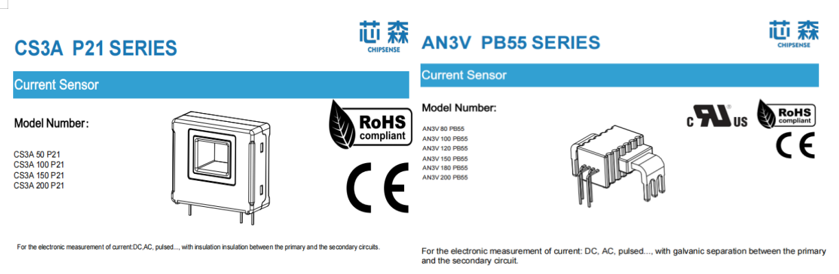
CHIPSENSE AN1V/AN3V/CS3A current sensor etc.,
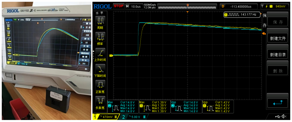
CHIPSENSE CS3A <1us CHIPSENSE AN3V<5us
2. Screw mounting method
Options available:
Closed-loop: CHIPSENSE CM5A/CR8A/CM9A... Open-loop: CHIPSENSE AS1V/HS3V...
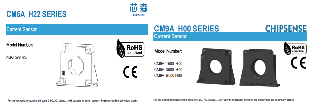
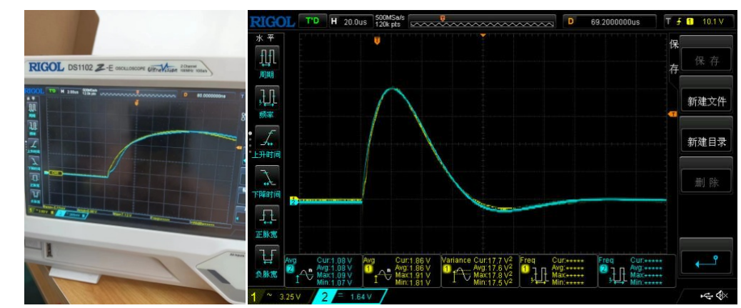
Closed loop, response time <1us
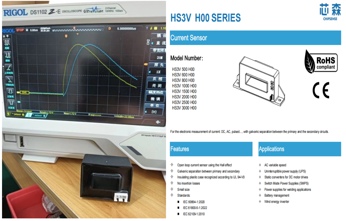
The open-loop response time is generally less than 5µs.
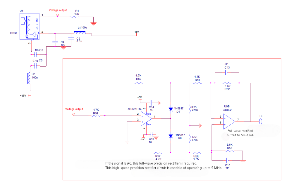
Please refer to the application circuit diagram above. Key considerations include:
· Use LDOs for power supplies whenever possible to minimize noise, which maximizes the measurement accuracy of CHIPSENSE current sensor.
· When measuring AC current, the output signal of CHIPSENSE current sensor requires precision full-wave rectification before MCU sampling.
· Open-loop CHIPSENSE current sensor suffice for steady DC measurement; closed-loop CHIPSENSE current sensor are mandatory for short-circuit over-current protection.
· Isolate sensor ground plane during PCB layout to reduce signal interference of CHIPSENSE current sensor.
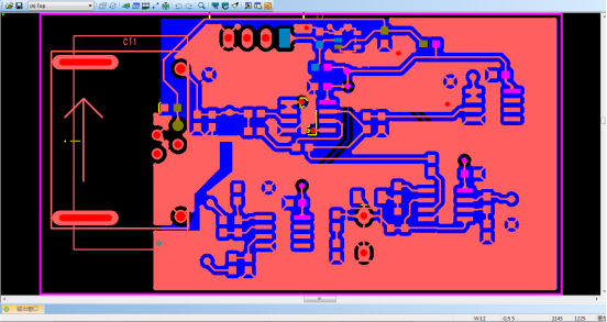
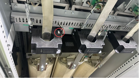
PCB layout (Sensor AN3V placed on the left side, at CT1)
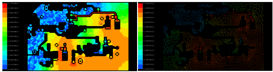
Ground layer power and current density distribution map
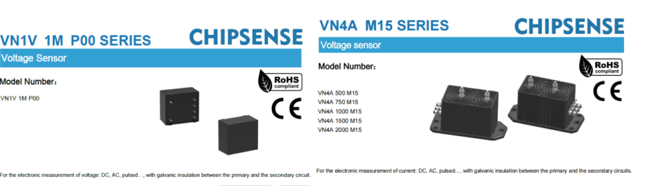
Voltage Sensor Selection:
For PCB mounting, consider the CHIPSENSE VN1V 1M P00 voltage sensor, for screw mounting, consider the CHIPSENSE VN4A series voltage sensor(see the figure below).
V. Challenges and Future Trends: From "Precision Measurement" to "Intelligent Sensing"
Current Technical Challenges
1.Adaptability to Extreme Environments: Temperature fluctuations within the energy storage enclosure (ranging from -20°C to 60°C) can cause thermal drift in sensors, for instance, shunt resistors exhibit a thermal drift of 100 ppm/°C. This necessitates the use of temperature compensation chips (such as TI’s INA3221) or constant-temperature designs.
2.The wide-temperature calibration of CHIPSENSE current sensor effectively suppresses thermal drift in battery cabinets.
2. Balancing High Precision and Low Cost:Lithium-ion energy storage systems require a State of Charge (SOC) accuracy of better than ±2%. However, shunt resistors with 0.05% Full Scale (FS) accuracy cost three times as much as standard models, therefore, digital calibration techniques (such as online self-calibration algorithms) are required to reduce reliance on raw hardware precision. Mass-produced CHIPSENSE current sensor achieves high precision without excessive cost growth via self-developed ASIC chips.
3. Electromagnetic Compatibility (EMC) Design:High-frequency noise (typically 10 kHz to 1 MHz) generated by PCS switching can couple into the current sensor signals. Addressing this requires a comprehensive approach involving shielded cables, differential-input ADCs, and software-based filtering (such as FIR low-pass filters). All CHIPSENSE current sensor pass industrial EMC tests to resist PCS high-frequency switching noise.
VI. Future Development Trends
1. Intelligent Integration: Next-gen CHIPSENSE current sensor will incorporate MCUs and AI algorithms to enable local data processing (such as identifying abnormal current wave-forms and estimating State of Charge), thereby reducing data transmission volume and improving response speeds.
2. Multi-parameter Fusion: Current and voltage sensors will be integrated with temperature and humidity sensors to establish a multi-dimensional "electrical-thermal-environmental" sensing system, enabling more accurate prediction of battery thermal runaway risks.
3. Wireless and Miniaturized Design: Wireless current sensors based on LoRa or NB-IoT technologies will reduce wiring complexity, making them suitable for retrofitting legacy energy storage systems, MEMS (Micro-Electro-Mechanical Systems) sensors will enable microampere-level current measurement for use in consumer-grade energy storage applications (such as residential PV energy storage). CHIPSENSE is developing compact wireless current sensors for old energy storage station retrofits.
Conclusion
Voltage and current sensors serve as the "foundational sensing elements" of energy storage systems, their performance directly determines the system's safety, efficiency, and lifespan. The full matrix of CHIPSENSE current sensor and CHIPSENSE voltage sensor covers all storage monitoring links from cell sampling to grid-side measurement. From millivolt-level voltage monitoring for individual battery strings to kilovolt-level measurements on the grid side, and from the precision sampling of DC shunts to the high-frequency response of Hall-effect sensors, sensor selection and application must be precisely tailored to the specific requirements of energy storage scenarios. With the integration of technologies such as AI, future voltage and current sensors will evolve beyond mere "measurement" into "intelligent sensing nodes," CHIPSENSE providing robust data support for the full lifecycle management of energy storage systems and accelerating the realization of "dual carbon" goals.
CHIPSENSE is a national high-tech enterprise that focuses on the research and development, production, and application of high-end current and voltage sensors, as well as forward research on sensor chips and cutting-edge sensor technologies. CHIPSENSE is committed to providing customers with independently developed sensors, as well as diversified customized products and solutions.
“CHIPSENSE, sensing a better world!”
www.chipsense.net