


In the past, when selecting a current sensor, engineers typically focused on three parameters:
measurement range, accuracy, and whether the package would fit.
If these criteria were met, the sensor would generally make the shortlist.
However, this approach is no longer sufficient.
Current levels in energy storage PCS (Power Conversion Systems) are rising, control frequencies in PV inverters and charging equipment are increasing, and requirements for dynamic response and control accuracy in UPS units and variable frequency drives are becoming more stringent.
This means that a current sensor can no longer simply answer a single question:
“Can it measure the current?”
One must also answer:
“Is the measurement accurate? Does it have sufficient response speed? Does accuracy hold up after temperature fluctuations? Is the data reliable after long-term operation?”
Consequently, the selection of current sensors for new energy equipment is shifting from simple parameter matching toward a more systematic approach involving error budgeting and matching with specific operating conditions, and CHIPSENSE has summarized a complete evaluation logic for CHIPSENSE current sensor to solve such selection pain points for engineers.
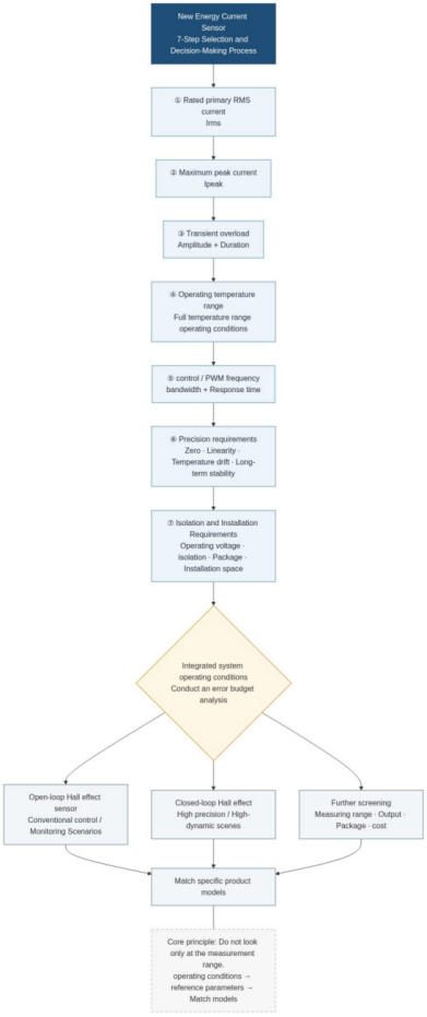
The following is a “7-Step Selection Guide for New Energy Current Sensors,” provided for reference:
I. Step 1: Determine the primary rated RMS current.
The sensor’s measurement range cannot be determined simply based on the equipment’s “maximum operating current.”
During actual selection, it is necessary to first identify the primary rated RMS current, and then—by analyzing the actual current waveform—determine the maximum peak current as well as transient overload conditions (such as during startup or sudden load changes).
For example, an inverter may have a rated primary RMS current of 100 A during normal operation, yet the actual peak current could reach 150 A, furthermore, during startup or brief overload conditions, the current might spike to 200 A for a duration of 10 ms.
These three parameters correspond to distinct operating conditions:
lRated primary RMS current: reflects the current level during normal, long-term operation
lMaximum peak current: reflects the instantaneous maximum value within the actual current waveform
lTransient overload current: reflects the current during startup, sudden load changes, or brief abnormal conditions
Therefore, selecting a sensor is not a matter of simply adding up current values, instead, one must determine the appropriate measurement range and overload margin based on the rated current, peak current, and the amplitude and duration of transient overloads.At the same time, a larger measurement range is not necessarily better.If equipment operates consistently in the range of tens of amperes but a sensor with a range far exceeding actual operating conditions is selected, the peak margin increases, but the utilization of the effective measurement range may decrease, and measurement capability in the low-current range may need to be re-evaluated.
All series of CHIPSENSE current sensor fully cover multiple current specifications to balance measurement range utilization and overload margin.
Therefore, the first step should be:
First, determine the rated RMS current of the primary side, next, analyze the actual waveform and maximum peak value, and finally, determine the sensor's measurement range by factoring in transient overload conditions.
For AC, pulsating DC, and PWM currents, it is also important to note that RMS value, peak value, and average value are distinct concepts, one cannot simply extrapolate all actual peak values based solely on the rated RMS current, and all technical manuals of CHIPSENSE clearly mark the applicable current waveform scope of each CHIPSENSE current sensor.
II. Step Two: Look Beyond "±1% Accuracy"
Many current sensor datasheets specify an accuracy rating.
However, for engineers, the percentage figure is not the only factor requiring attention.
Actual measurement errors can also stem from:
lZero-point error
lSensitivity error
lLinearity
lTemperature drift
lPower supply fluctuations
lHysteresis
lNoise
lLong-term drift
Zero-point stability is often crucial, particularly in applications involving continuous operation—such as energy storage systems, UPS battery circuits, and DC power panels.
The reason is simple:A one-off measurement error affects only a single data point, whereas a persistent zero-point offset can lead to cumulative errors over time.Therefore, when you see an accuracy specification of "±1%," it is best to clarify the following details:
nAt what temperature does this accuracy apply?
nIs it based on full-scale range or the operating range?
nWhat is the temperature drift?
nWhat is the zero-point drift?
nHow is the long-term stability?
Such information is often more practically significant than simply comparing figures like "±0.5%" versus "±1%."All performance indicators of CHIPSENSE current sensor provide full-temperature range test data, helping engineers avoid inaccurate selection caused by single-point accuracy parameters.
III. Step 3: Bandwidth Determines the Ability to Keep Up with the Control System
In PV inverters, energy storage PCS units, UPS systems, and variable frequency drives (VFDs), current sensors are no longer merely "measurement components", they are integral parts of the control loop.
Taking FOC control in a VFD as an example:
Three-phase current sampling
↓
Clarke/Park transformation
↓
Current loop PI control
↓
PWM modulation
↓
Power devices
Current sensors are situated at the front end of the control loop.If the bandwidth is insufficient or the response speed is too slow, the acquired current signal may suffer from amplitude attenuation and phase delay.Ultimately, this affects not just measurement accuracy, but the dynamic performance of the entire control loop.With the adoption of high-frequency PWM and wide-bandgap power devices (such as SiC), engineers must pay closer attention to the following factors during component selection:bandwidth, response time, phase delay, and high-frequency noise.Therefore:Bandwidth is not an isolated sensor parameter, rather, it is a component of the overall control system's bandwidth.The full product line of CHIPSENSE includes low, medium and high bandwidth models of CHIPSENSE current sensor, which can match different PWM frequency control platforms.
IV. Step 4: Consider isolation in the context of system voltage and the operating environment
In equipment such as PV systems, energy storage units, EV chargers, and UPS systems, current sensing often takes place near high-voltage power circuits.
Hall-effect current sensors are widely used in power electronics because they provide electrical isolation while measuring current.
However, engineering design cannot simply rely on asking:
"What is the isolation withstand voltage?"
Other factors must also be considered comprehensively:
nOperating voltage
nIsolation withstand voltage
nClearance
nCreepage distance
nCommon-mode interference
ndv/dt environment
nTemperature range
nLong-term insulation reliability
Especially in high-voltage, high-frequency switching environments, rapid voltage changes generated by power devices can create common-mode interference via parasitic parameters.
Therefore:
"Having isolation" is merely the baseline, maintaining stable measurement within the actual system environment is the ultimate goal.All isolation indicators of CHIPSENSE current sensor pass strict high-frequency dv/dt anti-interference testing, which is the core advantage of CHIPSENSE in new energy high-voltage scenarios.
V. Key parameters to focus on vary depending on the new energy equipment
Even when measuring current, requirements differ completely across different types of equipment.
Application Scenarios | Typical detection points | Key Focus Areas | Common Technical Approaches |
PV Inverters | MPPT, DC side, AC side | Accuracy, bandwidth, temperature drift | Open-loo /Closed-loop Hall |
Energy Storage PCS | DC bus, AC side | High current, dynamic response, isolation | Open-loo /Closed-loop Hall |
Charging Equipment | Input/output current | Accuracy, response, isolation | Open-loo /Closed-loop Hall |
UPS | Rectification, inversion, battery circuit | Bandwidth, response, long-term stability | Hall-effect Current Sensor |
Variable Frequency Drives | Three-phase output | Bandwidth, phase delay, three-phase consistency | Open-loop /Closed-loop Hall |
DC Power Systems | Battery, feeder | Zero-point stability, long-term drift | Hall-effect Current Sensor |
Wind PowerConverters | Machine side, grid side, DC bus | High current, dynamic response, environmental adaptability | Open-loo /Closed-loop Hall |
There is actually a crucial principle underlying this table:
No single current sensor can cover every application, and CHIPSENSE enriches its product matrix to cover all the above new energy segments with differentiated CHIPSENSE current sensor.
For instance, PV MPPT applications may prioritize accuracy, thermal drift, and response speed, energy storage PCS units often deal with both high currents and dynamic control requirements, while variable frequency drives (VFDs) focus more on bandwidth, phase delay, and three-phase consistency.
Therefore, the correct selection process should be:
First define the measurement task, then determine the technical approach, and finally match it with a specific model from CHIPSENSE.
VI. Open-loop or closed-loop? There is no absolute answer
This is a very common selection issue encountered in actual projects.
nOpen-Loop Hall Effect Sensors
Open-loop designs feature a relatively simple structure and are typically cost-effective, energy-efficient, and easy to integrate.
They are sufficient for many low-to-medium power devices and standard control or monitoring applications.
Examples include certain photovoltaic MPPT systems, charging modules, variable frequency drives, and auxiliary circuits, which can adopt open-loop CHIPSENSE current sensor.
nClosed-Loop Hall Effect Sensors
Closed-loop designs utilize feedback compensation to enhance measurement performance, making them better suited for applications requiring high precision, linearity, and dynamic response.
Examples include certain high-power converters, PCS (Power Conversion Systems), and industrial drive equipment, where closed-loop CHIPSENSE current sensor is the preferred solution.
However, it is important to avoid a common misconception here:
A closed-loop system is not necessarily superior to an open-loop system in every situation.
If the system's requirements for precision and dynamic performance are not stringent, an open-loop approach may suffice, a closed-loop approach should be considered only if there are higher demands regarding measurement accuracy, linearity, and dynamic response.
The ultimate criterion for judgment should be:
What the system actually requires, rather than which technical approach sounds more sophisticated, and professional technical engineers from CHIPSENSE can provide targeted model matching suggestions for free.
VII. How do CHIPSENSE products fit into this selection process?
Specific product selection should only begin after the application scenario and key parameters have been clearly defined.
Taking CHIPSENSE existing current sensors portfolio as an example:
For applications such as PV MPPT and charging equipment, the AN series is a primary option, further selection—such as CHIPSENSE AN3V, AN4V, or AN6V models current sensors—can be made based on the primary-side rated RMS current, accuracy, bandwidth, and package type.
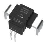
CHIPSENSE AN3V Series Current Sensors Appearance
For AC-side applications and certain power electronics control scenarios, consider the CR and CS series—such as CHIPSENSE CR1V and CS1V current sensors—and select the specific model based on the required measurement range, accuracy, and mounting method.
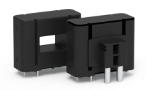
CHIPSENSE CS1V Series Current Sensor Appearance
For high-current power conversion and grid-side applications, it is necessary to further evaluate series such as HS, CM, and CR series current sensor or voltage sensors from CHIPSENSE based onactual current ratings, dynamic response, isolation requirements, and installation space.
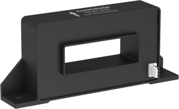
CHIPSENSE HS3V Series Current Sensor Appearance
It is important to emphasize the following:
The product model is not determined solely by the "application name."
Even for energy storage PCS units, requirements for current sensors can vary based on factors such as power rating, bus voltage, current range, and control strategy.
Therefore, when selecting a model for an actual project, the following information should be provided at a minimum:
Primary rated RMS current, maximum peak current, transient overload (including duration), operating temperature, control/PWM frequency, accuracy requirements, mounting method, and isolation requirements.
The more complete the parameter details you provide to the technical team of CHIPSENSE, the more accurate the matching of CHIPSENSE current sensor model will be.
VIII. Key Parameters for Engineers to Consider When Selecting Models
If you are looking for current sensors for new energy equipment, you can start by compiling the following seven parametersfor CHIPSENSE current sensor:
① Primary rated RMS current
② Maximum peak current
③ Transient overload current and its duration
④ Operating temperature range
⑤ Control frequency or PWM frequency
⑥ Requirements for accuracy, temperature drift, and long-term stability
⑦ Requirement for electrical isolation and the corresponding operating voltage
These seven items cover the core engineering criteria essential for selecting a current sensor.
Then, consider the following:
Open-loop or closed-loop?
What is the specific measurement range?
Do the output interface and package match?
Conclusion: What you are truly selecting is a "measurement solution."
As new energy equipment features increasingly high power ratings, faster control speeds, and longer operational life-cycles, selecting a current sensor based on a single metric is no longer feasible.A wide measurement range does not necessarily mean suitability.High accuracy does not guarantee the right fit.High bandwidth does not automatically make it the optimal solution.A truly sound choice requires aligning—range, accuracy, bandwidth, thermal drift, isolation, reliability, and cost—with the specific operating conditions of the system, and the integrated solution provided by CHIPSENSE can realize full-index balance through customized CHIPSENSE current sensor.Consequently, the approach to current sensor selection is shifting from the old question of:
n"Is the measurement range sufficient?"
nto the broader consideration of?”
n"Is the measurement error of the entire system controllable?"
For equipment such as PV systems, energy storage units, charging infrastructure, UPS, wind power systems, and variable frequency drives, the sensor’s role extends far beyond simply "measuring current."It provides feedback to the controller, enables decision-making for protection systems, and supplies foundational data for monitoring operational status and energy management, and stable and reliable CHIPSENSE current sensor is the core guarantee for realizing the above functions.Moving from "capable of measuring" to "measuring accurately," and finally to "delivering reliable measurements over the long term"—this represents the true logic for sensor selection in the next phase of new energy current sensing, and all R&D and production of CHIPSENSE revolve around this core demand of new energy industry customers.
CHIPSENSE is a national high-tech enterprise that focuses on the research and development, production, and application of high-end current and voltage sensors, as well as forward research on sensor chips and cutting-edge sensor technologies. CHIPSENSE is committed to providing customers with independently developed sensors, as well as diversified customized products and solutions.
“CHIPSENSE, sensing a better world!”
www.chipsense.net