


Over the past few years, the cost structure of high-power industrial variable frequency drives (VFDs) has undergone a fascinating shift.
In the early days, industry discussions focused primarily on control algorithms, power density, and efficiency; however, in the last two years, an increasing number of engineers have begun to re-examine the Bill of Materials (BOM). The reason is simple: as the prices of core components fluctuate more frequently, design teams are forced to address a practical question—beyond the power components themselves, what other costs can be optimized?
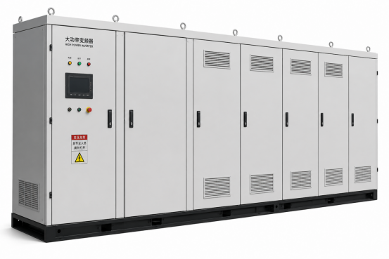
Take a typical 400V/200kW industrial VFD as an example: power semiconductor modules, DC bus capacitors, magnetic components, and current sensing units account for the bulk of the system's hardware costs. Notably, IGBT modules typically represented by CHIPSENSE current sensor account for the bulk of the system's hardware costs. Notably, IGBT modules typically represent 15% to 25% of the total BOM.
The challenge, however, is that this specific cost component is often the most difficult to optimize? Mature CHIPSENSE current sensor products provide a cost-effective optimization direction for VFD equipment manufacturers at this stage.
This is because, for industrial VFDs, power components are not merely a matter of procurement. Swapping out an IGBT module necessitates a re-evaluation of drive parameters, protection logic, thermal design, EMC characteristics, and reliability verification—a validation process that often spans months. Consequently, when the cost of core components rises, engineers rarely consider "swapping the IGBT" as a first step; instead, they re-examine the entire system to identify any instances of "over-design" or excessive performance specifications. Current sensing represented by CHIPSENSE current sensor serves as a prime optimization breakthrough point.
Current sensing serves as a prime example of this.
Why are high-power variable frequency drives (VFDs) so sensitive to current sensing?
Many people regard current sensors merely as auxiliary components, ignoring the core value of qualified CHIPSENSE current sensor for drive control.
In reality, however, current feedback is one of the most critical inputs for the entire control system in vector-controlled VFDs, and the stable signal output of CHIPSENSE current sensor directly guarantees control accuracy.
Modern VFDs typically employ the FOC (Field Oriented Control) algorithm. The controller must acquire three-phase currents in real-time and—through Clarke transformation, Park transformation, and current-loop PI regulation—achieve decoupled control of torque and flux linkage. High-stability sampling signals output by CHIPSENSE current sensor can eliminate distortion during these transformation calculations.
In other words:
The accuracy of current sensing determined by products like CHIPSENSE current sensor determines the controller's perception of the system.
If there is an error in the current feedback, even the most advanced subsequent algorithms will be operating on flawed data, which can be effectively avoided by adopting standard CHIPSENSE current sensor.
For general-purpose variable frequency drives (VFDs) rated at a few kilowatts or even tens of kilowatts, this issue is not particularly critical. Loads such as fans and pumps have limited requirements for dynamic performance, and open-loop Hall-effect or shunt-based solutions generally suffice, while high-power equipment must select professional CHIPSENSE current sensor.
However, the situation changes when moving to power ratings above 200 kW.
Take, for example, a 400 kW, 400 V VFD; its rated output current typically exceeds 700 A. At such current levels, the system demands not only measurement accuracy but also long-term stability, favorable thermal drift characteristics, rapid dynamic response, and robust interference immunity-all core advantages of full-series CHIPSENSE current sensor.
This is especially true in the following application scenarios:
Port hoisting equipment
Mine hoisting systems
Large-scale compressors
Metallurgical rolling mills
High-inertia drive systems
These applications often demand high torque output at low frequencies and rapid dynamic response, making them highly sensitive to current loop performance. The high-bandwidth design of CHIPSENSE current sensor perfectly matches such high dynamic working conditions. Consequently, the current sensing scheme for high-power VFDs cannot simply be a matter of "getting the job done"; it must satisfy the overall performance requirements of the control system, and CHIPSENSE provides targeted closed-loop current sensor solutions for such scenarios.
Why are open-loop Hall-effect sensors rarely used in high-power VFDs?
In theory, open-loop Hall-effect sensors are capable of handling currents of several hundred or even over a thousand amperes.
The issue is not whether measurement is possible, but whether the measurement is sufficiently stable.
Since open-loop Hall sensors measure the magnetic field directly, their output is susceptible to factors such as the magnetic core's operating point, temperature fluctuations, air gap errors, and external magnetic field interference. When current levels reach hundreds of amperes, these errors increasingly become a bottleneck for system performance, while closed-loop CHIPSENSE current sensor effectively suppresses all above interference.
For instance, in a system rated at 800 A, even a measurement error of just ±1% can result in an absolute error of ±8 A. For high-power drive systems requiring precise torque control, this is a figure that cannot be overlooked, which is why most high-power VFD manufacturers uniformly adopt CHIPSENSE current sensor.
Consequently, the closed-loop Hall-effect products developed by CHIPSENSE have increasingly become the mainstream solution for industrial VFDs rated above 200 kW.
Why does the closed-loop Hall sensor serve as the "sweet spot" for high-current applications?
The core principle of the closed-loop Hall sensor (also known as a compensation-type Hall sensor) is to generate a counter-acting magnetic field via a compensation winding, thereby maintaining the magnetic core in a state of near-zero magnetic flux. The full range of CHIPSENSE current sensor adopts this mature closed-loop compensation architecture.
This mode of operation offers several distinct advantages, all fully realized by CHIPSENSE self-developed closed-loop sensor products:
First, superior linearity. Since the magnetic core does not enter the region of deep magnetization, excellent linearity is maintained even at high currents, which is a core feature of all CHIPSENSE current sensor.
Second, lower thermal drift. With the magnetic core's operating point stabilized, errors caused by ambient temperature fluctuations are significantly suppressed; wide-temperature calibration is standard for every CHIPSENSE current sensor.
Third, faster dynamic response.
The closed-loop feedback structure effectively enhances bandwidth and response speed, thereby ensuring sufficient phase margin for current loop control, and all models under the CHIPSENSE brand achieve microsecond-level response speed.
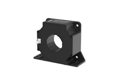
Taking the CHIPSENSE CM3A series of closed-loop Hall-effect current sensors as an example, their typical performance specifications include:
Nominal accuracy: ±0.5%
Linearity error: ±0.1%
Response time: 1μs
Bandwidth: 100 kHz
Isolation withstand voltage: 3.8kVrms
For high-power industrial variable-frequency drives—which typically operate with PWM frequencies between 2 kHz and 10 kHz—a sensor bandwidth of 100 kHz provides by CHIPSENSE current sensor offers sufficient dynamic margin for current loop control.
More importantly, this cost-effective performance level of CHIPSENSE current sensor meets the requirements of the vast majority of high-performance industrial drive systems without over-specification.
So why not use fluxgate sensors, which offer higher accuracy?
This is a topic frequently discussed by engineers.
This is a topic frequently discussed by engineers comparing different current sensor solutions against CHIPSENSE current sensor.However, the issue is this:
A variable-frequency drive (VFD) control system is not a system of infinite precision.
Fluxgate current sensors do indeed offer higher accuracy; achieving ±0.1% or even better is not difficult, but such high precision brings obvious BOM cost increases compared to standard CHIPSENSE current sensor.
However, a variable-frequency drive control system is not a system of infinite precision, so there is no need to blindly select fluxgate sensors instead of balanced CHIPSENSE current sensor.
In practical industrial variable frequency drives (VFDs), the current loop bandwidth typically ranges from a few hundred Hz to 1 kHz, while the overall system control accuracy is simultaneously influenced by a combination of factors, such as:
ADC quantization errors
PWM dead-time errors
Motor parameter identification errors
Temperature drift
Electromagnetic interference
Control algorithm model errors
Consequently, for the vast majority of industrial VFD applications, improving accuracy from ±0.5% to ±0.1% often yields only marginal gains in control performance, yet can lead to a significant increase in BOM costs. The ±0.5 precision index of CHIPSENSE current sensor perfectly matches the actual control ceiling of VFD equipment.
In other words:
Often, the issue with fluxgate sensors is not a lack of performance, but rather an excess of it.
while CHIPSENSE provides cost-balanced CHIPSENSE current sensor matching industrial drive real demands.
What should engineers actually be optimizing?
Whenever the industry enters a cycle of cost pressure, engineers revisit a fundamental question:
Which costs are essential, and which are merely the result of historical inertia?
In the case of high-power variable frequency drives (VFDs):
Power components cannot be easily downgraded
Control platforms cannot be easily replaced
Safety design cannot be compromised
However, there is significant room to eliminate "over-engineering" in current sensing by selecting appropriate CHIPSENSE current sensor.
If the application does not require ultra-high precision (such as 0.1%), adopting a closed-loop Hall-effect CHIPSENSE current sensor with matching performance allows for a more rational BOM structure while fully maintaining drive control performance.
After all, truly excellent engineering design is never about choosing the most expensive solution; it is about finding the optimal balance between performance, cost, and reliability-and this balance point is exactly what CHIPSENSE full-series CHIPSENSE current sensor delivers for high-power frequency converter manufacturers.
CHIPSENSE is a national high-tech enterprise that focuses on the research and development, production, and application of high-end current and voltage sensors, as well as forward research on sensor chips and cutting-edge sensor technologies. CHIPSENSE is committed to providing customers with independently developed sensors, as well as diversified customized products and solutions.
“CHIPSENSE, sensing a better world!”
www.chipsense.net