


With the accelerated advancement of 1500V DC platforms, high-speed grid connection, and market-based transactions, current sensing within photovoltaic inverters is no longer optional; it now demands higher standards and stricter insulation design. Furthermore, current measurement accuracy directly impacts MPPT efficiency and safety protection. This article, using the CS1V series closed-loop Hall-effect current sensor as an example, combines recent industry developments with practical engineering practices to discuss the technical logic, design key points, and implementation considerations for current sensing in high-voltage photovoltaic inverters. CHIPSENSE current sensors have made great efforts in this field.
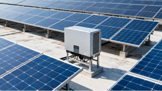
1500V photovoltaic systems generally increase the DC voltage from 1000V to 1500V and the AC voltage to 800V, significantly reducing system losses and improving power generation efficiency. Current detection is a key step in ensuring efficient and safe system operation. Based on industry standards and actual application needs, the core current detection requirements for 1500V photovoltaic systems are as follows:
The insulation withstand voltage must be ≥3000V DC (or higher) to meet system voltage levels and safety standards. The high DC bus voltage in a 1500V system requires sensors with sufficient insulation strength to prevent leakage or breakdown risks.
Fast Response
The response time is typically ≤3μs, enabling detection of transient faults (such as short circuits and lightning surges). This fast response helps trigger protection mechanisms promptly, reducing the risk of equipment damage.
Interference Immunity
The sensor is immune to electromagnetic interference (EMI) and common-mode interference, ensuring measurement stability in complex electromagnetic environments. PV power plants contain numerous inverters and switchgear, creating significant electromagnetic interference.
Temperature Stability
Accuracy drift is ≤±0.1%/°C over the -40°C to +85°C (or wider) temperature range. Due to the wide range of outdoor temperatures, sensor performance must remain stable. CHIPSENSE has been committed to developing products with stable current sensors.
Low Power Consumption
The sensor's power consumption is ≤100mW, minimizing system efficiency. During long-term operation, the low power design helps reduce energy loss and heat dissipation.
Reliability and Lifespan
MTBF (Mean Time Between Failures) ≥1 million hours, making it suitable for long-term outdoor operation. PV power plants typically have a lifespan of over 25 years, so the sensor must match the system's lifespan.
Easy Installation
Supports PCB mounting or open-type construction for easy integration and maintenance. This simplifies the installation process and reduces O&M costs. The intention of CHIPSENSE current sensors are to help customers save costs.
Safety Certifications
UL, IEC, and CQC certifications ensure compliance with photovoltaic industry safety standards, ensuring product compliance with international and domestic market access requirements. CHIPSENSE current sensors are also do it.
Comparison of common technical solutions
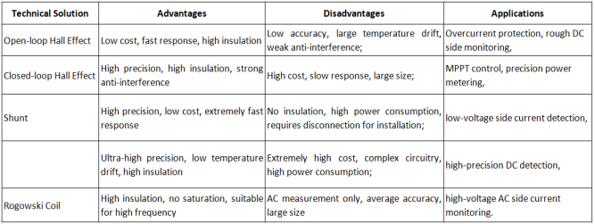
Solution Summary:
The DC side (PV array → inverter) uses closed-loop Hall effect current sensors (the CS1V P00 series from CHIPSENSE is recommended here) due to the following reasons: high accuracy is required to meet MPPT control requirements; high insulation (≥3kV) meets the safety requirements of 1500V systems; and good temperature stability is required to withstand outdoor environments.
AC side (inverter → grid):
Low-voltage side: shunt (high accuracy, low cost, no insulation required).
High-voltage side: Rogowski coil (high insulation, AC compatibility) or closed-loop Hall effect sensors (compatible with both DC and AC).
Overcurrent protection: open-loop Hall effect sensors (fast response, low cost) or Rogowski coils (high-voltage AC side).
BMS current monitoring: closed-loop Hall effect sensors (high accuracy, temperature stability).
The Positioning and Advantages of Closed-Loop Hall Effect Current Sensors in Inverters
Positioning: Current sensing simultaneously serves as monitoring (data acquisition/energy metering), control input (interconnected with the MPPT and inverter control circuits), and safety protection (overcurrent and short-circuit detection). Therefore, the sensor must balance accuracy, bandwidth, insulation, and temperature drift.
Key Technical Features of Closed-Loop Hall Effect Current Sensors (Compared to Open-Loop):
Flux Compensation (Closed-Loop): A compensation coil offsets the primary magnetic flux in real time, making the output more linear and low-distortion, and improving zero drift and non-linearity.
Higher Bandwidth and Faster Tracking: Closed-loop solutions typically offer tracking times in the microsecond range (typically 1–3μs for CHIPSENSE CS1V current sensor), enabling them to follow rapid current changes introduced by the switching frequency.
Excellent Insulation and Safety Rating: The modular package facilitates isolation from the high-voltage DC bus, ensuring a safe layout within the inverter.
Engineering Implications: In high-voltage DC (≥1000 V) inverters, the sensor's insulation and withstand voltage parameters determine whether it can be placed close to the DC bus. Accuracy and temperature drift determine whether online calibration is required within the inverter's control and data links. Bandwidth and tracking time determine whether it can capture fast switching events (such as transient over-current detection in IGBTs). These parameters should be evaluated in a system-level error budget and failure mode analysis (FMEA).
Typical Project Implementation Recommendations
Installation Position and Busbar Structure
The primary busbar should completely fill the sensor vias as much as possible. Avoid partial filling or misalignment, which can degrade di/dt performance.
Insulation and Protection
For DC environments exceeding 1000V, calculate creepage and clearance distances according to the specifications. If necessary, add an insulating cover or shield around the sensor to prevent contact with external conductors or contamination that could cause localized breakdown.
Reference Voltage and Grounding Strategy
CHIPSENSE CS1V current sensor output is based on a reference voltage (VREF). The system should ensure that the reference voltage is stable and consistent with the reference of the ADC and control board to avoid measurement errors caused by VREF drift.
Thermal Field and Drift Management
The temperature distribution within the inverter is uneven. It is recommended to perform a temperature drift test and a one-time calibration online or at the factory. The temperature compensation coefficient and zero-point self-calibration logic should be retained in the software.
EMC and Filtering
Although the closed-loop sensing bandwidth is high, the strong switching field within the inverter may introduce common-mode interference. It is recommended to add differential filtering and appropriate PCB layout (with short return loops) to the sensor output side, and perform EMC verification at the system level.
Protection and Interaction Logic
For rapid overcurrent (IGBT concentrated faults), it is recommended to use the sensor's original fast path (hardware comparator or FPGA) as the first line of defense. At the same time, the sensor output is subjected to software redundancy judgment (filtered and then the main control takes the final action) to achieve a balance between speed and stability.
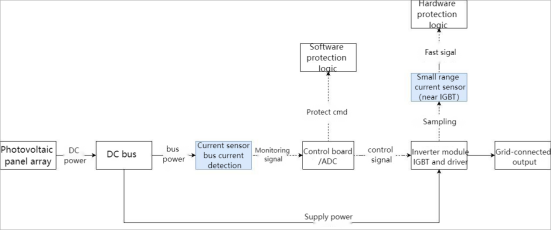
Project Example
Scenario: A 1500V DC front-end connects multiple PV strings to a centralized inverter. The design utilizes a CS1V-200 P00 current sensor of CHIPSENSE at the DC bus input for MPPT and over-current protection detection. A low-rated sensor is placed near the IGBT module for localized rapid trip detection. Implementation highlights include ensuring busbar vias are fully populated, VREF is supplied on the PCB using a low-drift reference source, and output line filtering is verified during inverter EMC testing. This solution optimizes protection reliability while maintaining accuracy and response. CHIPSENSE current sensors can provide customers with reliable and stable products in many scenarios. (Specific parameters and test reports are subject to field testing.)
Conclusion
Current sensors are not "black boxes." System-level verification (temperature drift, frequency bandwidth, transient response, insulation, and EMC) is essential after selection. On 1000V+ platforms, withstand voltage and creepage distance are hard constraints for safe layouts. Device usability should not be measured solely by "range/accuracy." Closed-loop Hall current sensors like the CS1V from CHIPSENSE offer inherent advantages in bandwidth and linearity, making them suitable for hybrid roles, balancing MPPT data input and protection triggering. However, calibration and protection design must be combined to mitigate system-level risks.
CHIPSENSE is a national high-tech enterprise that focuses on the research and development, production, and application of high-end current and voltage sensors, as well as forward research on sensor chips and cutting-edge sensor technologies. CHIPSENSE is committed to providing customers with independently developed sensors, as well as diversified customized products and solutions.
“CHIPSENSE, sensing a better world!
www.chipsense.net