


As we all know, "double carbon" refers to "peak carbon dioxide emissions" and "carbon neutrality". In the "double carbon" strategy, our country's photovoltaic power generation plays a main role. According to the data of the National Energy Administration, in the first half of this year, the new installed capacity of renewable energy in the country was 268 million kilowatts, of which solar power generation added 212 million kilowatts, and other hydropower, wind power and biomass power generation accounted for only a fraction. The main reasons for the rapid development of photovoltaic power generation are low cost, mature technology, wide application, simple operation and maintenance, etc. This article mainly talks about how current sensors can help MPTT improve the efficiency of photovoltaic power generation in the application of photovoltaic inverters. Taking CHIPSENSE current sensor as an example.
Brief description of photovoltaic inverter
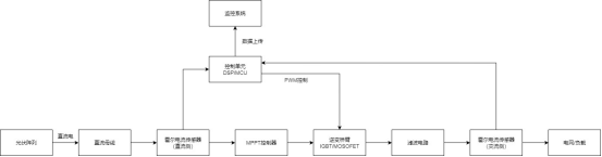
The solar energy AC power generation system is composed of solar panels, charge controllers, inverters and storage batteries. The core role of the inverter in the photovoltaic power generation system is to convert the direct current generated by the photovoltaic panel into AC power required by the grid or load, and ensure the smooth operation of the system and improve power generation efficiency. Its core functions are:
1. Power conversion: Converting direct current (DC) generated by photovoltaic panels into alternating current (AC) to meet the needs of the power grid or electrical equipment.
2. Maximum power tracking (MPPT): dynamically adjust the operating point of photovoltaic modules to ensure that each component is in the best power output state at the same time, maximizing system efficiency.
3. Grid interaction and protection: Monitor the state of the grid and automatically adjust the output power to adapt to changes in the grid; disconnect in the event of a failure to ensure system safety.
4. System optimization and maintenance: Optimize the performance of photovoltaic modules through intelligent algorithms to extend equipment life and reduce maintenance costs.
The core role of current detection in photovoltaic inverters
In a photovoltaic inverter, current detection is the core link to ensure the safety and efficient operation of the system, which directly affects the safety, efficiency and stability of the system.
1) In terms of safety, by monitoring the input/output current of the inverter in real time, any abnormalities such as over-current or short circuit can be immediately triggered to protect the inverter from damage or fire risk.
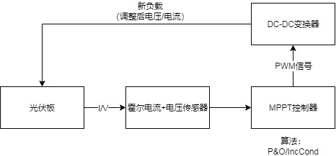
2) In terms of optimizing system power generation, there are two main core applications: 1. MPPT, the inverter integrates the maximum power point tracking (MPPT) technology to obtain the maximum possible power from the solar panel. MPPT collects the current data of the photovoltaic array in real time through current detection and cooperates with the Hall voltage sensor to provide complete IV (current-voltage) characteristic data, adjusts the working point, and ensures that the photovoltaic panel operates at the maximum power point, thereby improving power generation efficiency.
2. Power factor correction (PFC), in a grid-connected inverter, by detecting the AC current and adjusting the output waveform to be in phase with the grid voltage, improve the power factor and reduce reactive power loss.
3. Guarantee power quality, harmonic suppression: detect the harmonic components in the output current, adjust the switching state of the inverter through control algorithms (such as PWM), reduce harmonic injection into the grid, and comply with grid-connected standards (such as IEEE 1547).
In addition to the above common functions, current detection can also provide functions such as fault diagnosis and data monitoring as well as remote management for inverters: long-term current data can be used to analyze the aging trend of components (such as IGBTs and capacitors) to warn potential faults in advance; quickly locate fault modules through abnormal current waveforms (such as imbalances and burrs) to shorten maintenance time; upload current data to the monitoring system to help operation and maintenance personnel remotely monitor the running status of inverters, optimize energy management, and combine voltage data to calculate system efficiency, providing a basis for energy optimization. CHIPSENSE current sensors have many advantages and disadvantages.
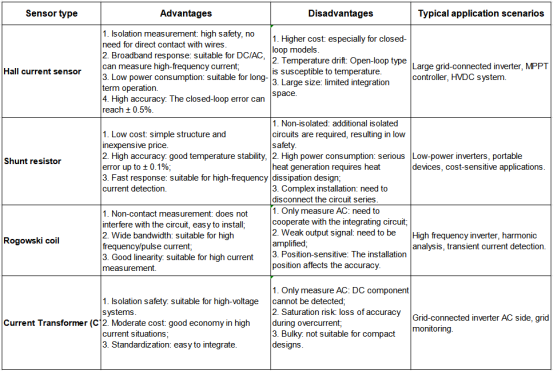
Inverter current detection scheme comparison
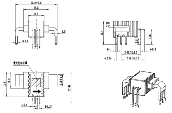
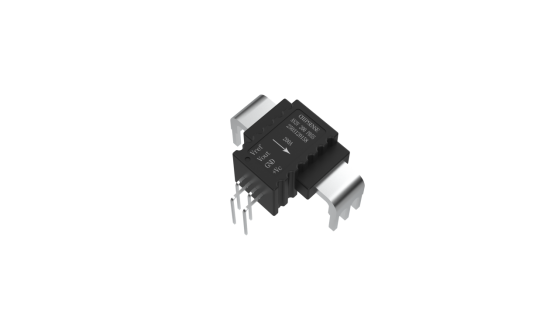
The Hall current sensor can be selected by CHIPSENSE AN3V PB55 series current sensor. The device of CHIPSENSE is compact, with a length, width and height of only 22.2 * 17.09 * 12.4mm. The primary current row is tin-plated with copper, which is easy to solder to the circuit board. its size:
Typical circuit application diagram:
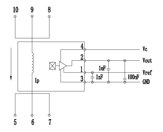
Typical application diagram of Hall current sensor in photovoltaic inverter
Introduction to AN3V PB55current sensor of CHIPSENSE
AN3V current sensor is an open-loop Hall current sensor product series independently developed by CHIPSENSE, which is designed to meet the high reliability and high consistency requirements of current measurement in power supply, photovoltaic, energy storage and other fields. The series current sensor from CHIPSENSE of materials, structures, designs and other aspects have been upgraded and optimized, and at the same time, CHIPSENSE current sensor is cost-effective, making it a high-quality choice for domestic alternatives.
The new products of CHIPSENSE AN3V series current sensors mainly include AN3V PB35/PB55 models, with a rated measurement range of 80A to 200A. CHIPSENSE not only does it ensure measurement accuracy, but also greatly improves the dynamic measurement range, reliability and excellent linearity.
Product features:
Open Loop Current Sensor Based on Hall Principle
Insulation between primary and secondary sides
Raw materials comply with UL 94-V0
No insertion loss
Power supply voltage: + 3.3V
Height h = 8.7mm
Execution standards:
IEC 60664-1:2020
IEC 61800-5-1:2022
IEC 6 2109-1: 2010
Parameter characteristics:
voltage output
Power supply: + 5V/3.3V
Rated range: ± 80~ 200A
Measuring range: ± 80~ 375A
Working range: -40~ 105 ° C
Typical Accuracy: 1%
Response time: 2.5 μs
Insulation voltage: 3kV
Bandwidth: 250kHz
Linearity: 0.5%
Conclusion
Current sensors are not only the key to safety in photovoltaic inverters, but also the core technology to improve MPPT efficiency, optimize power quality and realize remote intelligent management. Hall current sensors (such as CHIPSENSE AN3V series current sensor) are ideal for current detection of photovoltaic inverters due to their high precision, fast response and insulation design. CHIPSENSE current sensor also will be a good choice.
CHIPSENSE is a national high-tech enterprise that focuses on the research and development, production, and application of high-end current and voltage sensors, as well as forward research on sensor chips and cutting-edge sensor technologies. CHIPSENSE is committed to providing customers with independently developed sensors, as well as diversified customized products and solutions.
“CHIPSENSE, sensing a better world!
www.chipsense.net